IDT Transparent Mode Operation
Generic PCI to PCI Bridge Register Definition
PES12N3 User Manual
9 - 51
June 7, 2006
Notes
VCR0CAP- VC Resource 0 Capability (0x110)
VCR0CTL- VC Resource 0 Control (0x114)
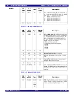
11:10
PATBLSIZ
RO
0x1
Port Arbitration Table Entry Size. This field indicates the
size of the port arbitration table in the device. The value in
the PES12N3 is set to 0x1 to indicate a 2-bit table.
0x0 - (bit1) Port arbitration table is 1-bit
0x1 - (bit2) Port arbitration table is 2-bits
0x2 - (bit4) Port arbitration table is 4-bits
0x3 - (bit8) Port arbitration table is 8-bits
31:12
Reserved
RO
0x0
Bit
Field
Field
Name
Type
Default
Value
Description
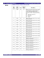
7:0
PARBC
RO
0x3
Port Arbitration Capability. This field indicates the type of
port arbitration supported by the VC. Each bit corresponds
to a Port Arbitration capability. When more than one arbi-
tration scheme is supported, multiple bits may be set.
The PES12N3 supports hardware fixed round robin and
weighted round robin with 32 phases.
bit 0 - hardware fixed round robin
bit 1 - weighted round robin with 32 phases
bit 2 - N/A
bit 3 - N/A
bit 4 - N/A
bit 5 - N/A
13:8
Reserved
RO
0x0
14
APS
RO
0x0
Advanced Packet Switching. Not supported.
15
RJST
RO
0x0
Reject Snoop Transactions. Not supported for switch
ports.
22:16
MAXTS
RO
0x0
Maximum Time Slots. Since this VC does not support
time-based WRR, this field is not valid.
23
Reserved
RO
0x0
31:24
PATBLOFFSET
RO
0x2
Port Arbitration Table Offset. This field contains the off-
set of the port arbitration table from the base address of the
Virtual Channel Capability structure in double quad words
(16 bytes).
Bit
Field
Field
Name
Type
Default
Value
Description
7:0
TCVCMAP
bit 0 RO
bits 1
through
7
RW
0xFF
TC/VC Map. This field indicates the TCs that are mapped
to the VC resource. Each bit corresponds to a TC. When a
bit is set, the corresponding TC is mapped to the VC.
Bit
Field
Field
Name
Type
Default
Value
Description
Summary of Contents for 89HPES12N3
Page 10: ...IDT Table of Contents PES12N3 User Manual iv June 7 2006 Notes...
Page 14: ...IDT List of Figures PES12N3 User Manual viii June 7 2006 Notes...
Page 36: ...IDT Clocking Reset and Initialization Reset PES12N3 User Manual 2 8 June 7 2006 Notes...
Page 40: ...IDT Link Operation Slot Power Limit Support PES12N3 User Manual 3 4 June 7 2006 Notes...
Page 50: ...IDT Switch Operation Switch Core Errors PES12N3 User Manual 4 10 June 7 2006 Notes...
Page 54: ...IDT Power Management Active State Power Management PES12N3 User Manual 5 4 June 7 2006 Notes...
Page 62: ...IDT Hot Plug and Hot Swap Hot Swap PES12N3 User Manual 6 8 June 7 2006 Notes...
Page 78: ...IDT SMBus Interfaces Slave SMBus Interface PES12N3 User Manual 7 16 June 7 2006 Notes...
Page 148: ...IDT Test and Debug SerDes Test Clock PES12N3 User Manual 10 6 June 7 2006...
Page 158: ...IDT JTAG Boundary Scan Usage Considerations PES12N3 User Manual 11 10 June 7 2006 Notes...


