IDT Transparent Mode Operation
Generic PCI to PCI Bridge Register Definition
PES12N3 User Manual
9 - 60
June 7, 2006
Notes
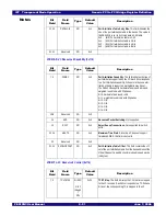
TMCNT2 - Test Mode Count 2 (0x0D4)
System Integrity
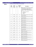
SWSICTL - Switch System Integrity Control (0x500)
Bit
Field
Field
Name
Type
Default
Value
Description
15:0
TMERRCNT4
RCW
0x0
Test Mode Error Count 4. When the switch is configured
to operate in a SerDes test mode, and an error is detected
in port and lane specified by the TMCNTPSEL4 and
TMCNTLSEL4 fields in the TMCNTCFG register, then the
value in this field in incremented.
This counter saturates at its maximum value.
This field is atomically cleared when read.
31:16
TMERRCNT5
RCW
0x0
Test Mode Error Count 5. When the switch is configured
to operate in a SerDes test mode, and an error is detected
in port and lane specified by the TMCNTPSEL5 and
TMCNTLSEL5 fields in the TMCNTCFG register, then the
value in this field in incremented.
This counter saturates at its maximum value.
This field is atomically cleared when read.
Bit
Field
Field
Name
Type
Default
Value
Description
0
DEEPC
RW
0x0
Disable End-to-End Parity Checking. When this bit is
set, end-to-end parity is not checked by the port and errors
are never generated. End-to-end parity is always computed
for data sent by the port to the switch core and cannot be
disabled.
1
SEEPC
RW
0x0
Silent End-to-End Parity Checking. When this bit is set
and end-to-end parity checking is enabled, end-to-end par-
ity errors detected at the port are logged in the EEPERRC
field in the SWSIPECNT register but no other action is
taken (i.e., TLP is not nullified, error non-fatal is not gener-
ated, and the DPE bit in the PCISTS register is not set)
2
GBEEP
RW
0x0
Generate Bad End-to-End Parity. When this bit is set,
bad parity is generated for all double words in TLPs emit-
ted to the switch core (i.e., those received on the ingress
port or generated by the port) whose TLP header Length
field (i.e., bits seven through zero of byte zero of the TLP
header) match the value in the Error Match Length
(Length) field in this register
3
SPTLPTO
RW
0x0
Silent Posted TLP Time-out. When this bit is set and a
TLP is dropped since it has been in a posted input buffer
for more than 50ms, then the error is logged in the PTLP-
TOC field in the SWSITDCNT register but no other action
is taken (i.e., error non-fatal is not generated).
7:4
Reserved
RO
0x0
Summary of Contents for 89HPES12N3
Page 10: ...IDT Table of Contents PES12N3 User Manual iv June 7 2006 Notes...
Page 14: ...IDT List of Figures PES12N3 User Manual viii June 7 2006 Notes...
Page 36: ...IDT Clocking Reset and Initialization Reset PES12N3 User Manual 2 8 June 7 2006 Notes...
Page 40: ...IDT Link Operation Slot Power Limit Support PES12N3 User Manual 3 4 June 7 2006 Notes...
Page 50: ...IDT Switch Operation Switch Core Errors PES12N3 User Manual 4 10 June 7 2006 Notes...
Page 54: ...IDT Power Management Active State Power Management PES12N3 User Manual 5 4 June 7 2006 Notes...
Page 62: ...IDT Hot Plug and Hot Swap Hot Swap PES12N3 User Manual 6 8 June 7 2006 Notes...
Page 78: ...IDT SMBus Interfaces Slave SMBus Interface PES12N3 User Manual 7 16 June 7 2006 Notes...
Page 148: ...IDT Test and Debug SerDes Test Clock PES12N3 User Manual 10 6 June 7 2006...
Page 158: ...IDT JTAG Boundary Scan Usage Considerations PES12N3 User Manual 11 10 June 7 2006 Notes...


