IDT Switch Operation
Introduction
PES12N3 User Manual
4 - 2
June 7, 2006
Notes
A flow control mechanism exists between the switch buffers and the transaction layer in the ingress
stack to prevent overflows. This flow control mechanism forms the basis of the PCIe flow control credits
advertised by the stack to the ingress port’s link partner. When a TLP is sent to the switch core from an
ingress stack, its header is looked-up in a routing map table and the TLP is queued in a buffer that corre-
sponds to the TLP type (i.e., posted, non-posted or completion).
Scheduling of a TLP to be forwarded from an input buffer to an egress stack is performed by an egress
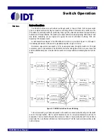
scheduler and port arbiter associated with each egress stack. Thus, the PES12N3 has three egress sched-
uler and three port arbiters. A flow control mechanism exists between the egress scheduler and the trans-
action layer in the egress stack. This flow control mechanism ensures that only TLPs which may be
accepted by the egress stack’s link partner are forwarded through the switch.
TLPs are routed in a cut-through manner through the PES12N3 if the ingress link width is greater than
or equal to the egress link width. If the ingress link width is less than the egress link width, then the entire
TLP must be received before it is forwarded. The egress scheduler selects the TLP from each ingress port
that may be forwarded to the associated egress port. If multiple ingress ports have TLPs which may be
forwarded to the same egress port, the port scheduler selects the ingress port from which a TLP is
forwarded.
Associated with each TLP in an input buffer is a timestamp. An egress scheduler always selects the TLP
in the input buffer that contains the oldest timestamp. If that TLP is destined for a different egress port, then
the egress scheduler makes no selection for that input port (i.e., TLPs are always forwarded from an
ingress port in chronological order). TLP timestamps are also used to discard any TLP from the head of an
input buffer that is more than 50 ms old. See section Switch Time-Outs on page 4-5 for additional details.
In making its selection, the egress scheduler considers the PCIe ordering rules. The PES12N3 supports
relaxed ordering for requests as well as completions. When the Disable Relaxed Ordering (DRO) bit is set
in the port A Switch Control (SWCTL) register, the switch strongly orders all transactions regardless of the
state of the relaxed ordering bit in TLPs.
The port scheduler associated with each egress port in the PES12N3 supports hardwired round robin
and weighted round robin with 32 phases. Both of these algorithms only arbitrate TLP requests and do not
consider bandwidth consumption.
In addition to the input buffers in the switch core, each egress stack contains a replay FIFO. When the
replay buffer fills, backpressure is provided to the switch core and no TLPs are forwarded to that egress
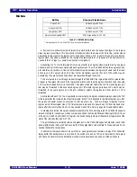
port. Table 4.2 enumerates the default flow control credits advertised by each port of the switch core.
Buffer
Size and Limitations
Posted FIFO
4 KB and up to 32 TLPs
Non-posted FIFO
1 KB and up to 32 TLPs
Completions FIFO
4 KB and up to 32 TLPs
Egress Stack Replay Buffer
1
1.
Stored with each TLP is a 32-bit LCRC as well as other information.
5120 bytes and up to 15 TLPs
Table 4.1 PES12N3 Buffer Sizes
Summary of Contents for 89HPES12N3
Page 10: ...IDT Table of Contents PES12N3 User Manual iv June 7 2006 Notes...
Page 14: ...IDT List of Figures PES12N3 User Manual viii June 7 2006 Notes...
Page 36: ...IDT Clocking Reset and Initialization Reset PES12N3 User Manual 2 8 June 7 2006 Notes...
Page 40: ...IDT Link Operation Slot Power Limit Support PES12N3 User Manual 3 4 June 7 2006 Notes...
Page 50: ...IDT Switch Operation Switch Core Errors PES12N3 User Manual 4 10 June 7 2006 Notes...
Page 54: ...IDT Power Management Active State Power Management PES12N3 User Manual 5 4 June 7 2006 Notes...
Page 62: ...IDT Hot Plug and Hot Swap Hot Swap PES12N3 User Manual 6 8 June 7 2006 Notes...
Page 78: ...IDT SMBus Interfaces Slave SMBus Interface PES12N3 User Manual 7 16 June 7 2006 Notes...
Page 148: ...IDT Test and Debug SerDes Test Clock PES12N3 User Manual 10 6 June 7 2006...
Page 158: ...IDT JTAG Boundary Scan Usage Considerations PES12N3 User Manual 11 10 June 7 2006 Notes...


