IDT Switch Operation
Interrupts
PES12N3 User Manual
4 - 7
June 7, 2006
Notes
The PME Lock Error (PMELOCK) bit in the PA_SWSTS register is set and the transaction is dropped
when a PME_Turn_Off message is received by a locked downstream PCI-PC I bridge (i.e., that associated
with port B or C). If error reporting is enabled, an ERR_NON_FATAL message is sent to the root when the
switch is unlocked.
The locked status of the switch may be determined by examining the Lock Mode (LOCK-MODE) bit in
the PA_SWSTS register
Interrupts
The PES12N3 supports legacy PCI INTx emulation where x is A, B, C or D. Rather than use sideband
INTx signals, PCIe defines two messages that indicate the assertion and negation of an interrupt signal. An
Assert_INTx message is used to signal the assertion of an interrupt signal and an Deassert_INTx message
is used to signal its negation.
The PES12N3 maintains an aggregated INTx state for each of the four interrupt signals (i.e., A through
D). The value of the INTA, INTB, INTC and INTD aggregated state may be determined by examining the
corresponding fields in the PA_SWSTS register. The aggregated INTx state of each port for each of the four
interrupt signals (i.e., A through D) on the primary side of its PCI to PCI bridge may be determined by exam-
ining the state of the INTA, INTB, INTC and INTD fields in the corresponding port’s Interrupt Status
(PA_INTSTS, PB_INTSTS, and PC_INTSTS) register.
An Assert_INTx message is sent to the root by the upstream port (i.e., port A), when the aggregated
state of the corresponding interrupt in the switch transitions from a negated to an asserted state. A
Deassert_INTx message is sent to the root by the upstream port when the aggregated state of the corre-
sponding interrupt transitions from an asserted to a negated state.
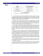
Table 4.4 exhibits the interrupt sources that are aggregated by the switch.
PCI to PCI bridges must map interrupts on the secondary side of the bridge according to the device
number of the device on the secondary side of the bridge. No mapping is performed for the PCI to PCI
bridges corresponding to downstream ports as these ports only connect to device zero. A mapping is
performed for the upstream port (i.e., port A).This mapping is summarized in Table 4.6 for the PES12N3.
PCI Compatible
INTx
Interrupt Sources
INTA
- External downstream port B
- External downstream port C
- Port B PCI-PCI bridge (hot-plug)
INTB
- External downstream port B
- External downstream port C
- Port C PCI-PCI bridge (hot-plug)
INTC
- External downstream port B
- External downstream port C
INTD
- External downstream port B
-External downstream port C
Table 4.4 PCI Compatible INTx Aggregation
Summary of Contents for 89HPES12N3
Page 10: ...IDT Table of Contents PES12N3 User Manual iv June 7 2006 Notes...
Page 14: ...IDT List of Figures PES12N3 User Manual viii June 7 2006 Notes...
Page 36: ...IDT Clocking Reset and Initialization Reset PES12N3 User Manual 2 8 June 7 2006 Notes...
Page 40: ...IDT Link Operation Slot Power Limit Support PES12N3 User Manual 3 4 June 7 2006 Notes...
Page 50: ...IDT Switch Operation Switch Core Errors PES12N3 User Manual 4 10 June 7 2006 Notes...
Page 54: ...IDT Power Management Active State Power Management PES12N3 User Manual 5 4 June 7 2006 Notes...
Page 62: ...IDT Hot Plug and Hot Swap Hot Swap PES12N3 User Manual 6 8 June 7 2006 Notes...
Page 78: ...IDT SMBus Interfaces Slave SMBus Interface PES12N3 User Manual 7 16 June 7 2006 Notes...
Page 148: ...IDT Test and Debug SerDes Test Clock PES12N3 User Manual 10 6 June 7 2006...
Page 158: ...IDT JTAG Boundary Scan Usage Considerations PES12N3 User Manual 11 10 June 7 2006 Notes...


