IDT Transparent Mode Operation
Generic PCI to PCI Bridge Register Definition
PES12N3 User Manual
9 - 40
June 7, 2006
Notes
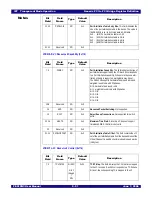
MSIUADDR - Message Signaled Interrupt Upper Address (0x084)
MSIMDATA - Message Signaled Interrupt Message Data (0x088)
Switch Control and Status Registers
Bit
Field
Field
Name
Type
Default
Value
Description
31:0
UADDR
RW
0x0
Upper Message Address. This field specifies the upper
portion of the DWORD address of the MSI memory write
transaction. If the contents of this field are non-zero, then
64-bit address is used in the MSI memory write transaction.
If the contents of this field are zero, then the 32-bit address
specified in the MSIADDR field is used.
Bit
Field
Field
Name
Type
Default
Value
Description
15:0
MDATA
RW
0x0
Message Data. This field contains the lower 16-bits of data
that are written when a MSI is signalled.
31:16
Reserved
RO
0x0
Reserved.
Bit
Field
Field
Name
Type
Default
Value
Description
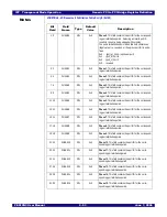
3:0
SWMODE
RO
HWINIT
Switch Mode. The value of this field encodes the switch
mode sampled on the Switch Mode
(SWMODE[3:0]) signals when exiting reset.
0x0 - (transparent) Transparent mode
0x1 - (transaprentinit) Transparent mode with serial
EEPROM initialization
0x2 through 0x7 - Reserved
0x8 - (loopback10) 10-bit loopback test mode
0x9 - Reserved
0xA - (intprbs) Internal pseudo random bit stream self-test
test mode
0xB - (extprbs) External pseudo random bit stream self-
test test mode
0xC - Reserved
0xD - (sbroadcast) SerDes broadcast test mode
0xE - 0xF Reserved
4
CCLKDS
RO
HWINIT
Common Clock Downstream. This bit reflects the value
of the CCLKDS signal sampled during the fundamental
reset.
5
CCLKUS
RO
HWINIT
Common Clock Upstream. This bit reflects the value of
the CCLKUS signal sampled during the fundamental reset.
6
MSMBSMODE
RO
HWINIT
Master SMBus Slow Mode. This bit reflects the value of
the MSMBSMODE signal sampled during the fundamental
reset.
Summary of Contents for 89HPES12N3
Page 10: ...IDT Table of Contents PES12N3 User Manual iv June 7 2006 Notes...
Page 14: ...IDT List of Figures PES12N3 User Manual viii June 7 2006 Notes...
Page 36: ...IDT Clocking Reset and Initialization Reset PES12N3 User Manual 2 8 June 7 2006 Notes...
Page 40: ...IDT Link Operation Slot Power Limit Support PES12N3 User Manual 3 4 June 7 2006 Notes...
Page 50: ...IDT Switch Operation Switch Core Errors PES12N3 User Manual 4 10 June 7 2006 Notes...
Page 54: ...IDT Power Management Active State Power Management PES12N3 User Manual 5 4 June 7 2006 Notes...
Page 62: ...IDT Hot Plug and Hot Swap Hot Swap PES12N3 User Manual 6 8 June 7 2006 Notes...
Page 78: ...IDT SMBus Interfaces Slave SMBus Interface PES12N3 User Manual 7 16 June 7 2006 Notes...
Page 148: ...IDT Test and Debug SerDes Test Clock PES12N3 User Manual 10 6 June 7 2006...
Page 158: ...IDT JTAG Boundary Scan Usage Considerations PES12N3 User Manual 11 10 June 7 2006 Notes...


