IDT Transparent Mode Operation
Generic PCI to PCI Bridge Register Definition
PES12N3 User Manual
9 - 45
June 7, 2006
Notes
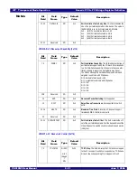
GPIOCS - General Purpose I/O Control and Status (0x0A8)
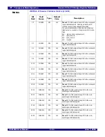
SMBUSSTS - SMBus Status (0x0AC)
Bit
Field
Field
Name
Type
Default
Value
Description
7:0
GPIOFUNC
RW
0x0
GPIO Function. Each bit in this field controls the corre-
sponding GPIO pin. When set to a one, the corresponding
GPIO pin operates as the alternate function as defined in
Chapter 8, General Purpose I/O. When a bit is cleared to a
zero, the corresponding GPIO pin operates as a general
purpose I/O pin.
15:8
GPIOCFG
RW
0x0
GPIO Configuration. Each bit in this field controls the cor-
responding GPIO pin. When a bit is configured as a gen-
eral purpose I/O pin and the corresponding bit in this field is
set, then the pin is configured as a GPIO output. When a
bit is configured as a general purpose I/O pin and the cor-
responding bit in this field is zero, then the pin is configured
as an input. When the pin is configured as an alternate
function, the behavior of the pin is defined by the alternate
function.
23:16
GPIOD
RW
HWINIT
GPIO Data. Each bit in this field controls the corresponding
GPIO pin. Reading this field returns the current value of
each GPIO pin regardless of GPIO pin mode (i.e., alternate
function or GPIO pin). Writing a value to this field causes
the corresponding pins which are configured as GPIO out-
puts to change state to the value written.
31:24
Reserved
RO
0x0
Reserved field.
Bit
Field
Field
Name
Type
Default
Value
Description
0
Reserved
RO
0x0
Reserved field.
7:1
SSMBADDR
RO
HWINIT
Slave SMBus Address. This field contains the SMBus
address assigned to the slave SMBus interface.
8
Reserved
RO
0x0
Reserved field.
15:9
MSMBADDR
RO
HWINIT
Master SMBus Address. This field contains the SMBus
address assigned to the master SMBus interface.
16
Reserved
RO
0x0
Reserved field.
23:17
IOEADDR
RWL
0x0
Hot-plug I/O Expander Master SMBus Address. This
field contains SMBus address assigned to the hot-plug I/O
expander on the master SMBus interface.
24
EEPROMDONE
RO
0x0
Serial EEPROM Initialization Done. When the switch is
configured to operate in a mode in which serial EEPROM
initialization occurs during a fundamental reset, this bit is
set when serial EEPROM initialization completes or when
an error is detected.
Summary of Contents for 89HPES12N3
Page 10: ...IDT Table of Contents PES12N3 User Manual iv June 7 2006 Notes...
Page 14: ...IDT List of Figures PES12N3 User Manual viii June 7 2006 Notes...
Page 36: ...IDT Clocking Reset and Initialization Reset PES12N3 User Manual 2 8 June 7 2006 Notes...
Page 40: ...IDT Link Operation Slot Power Limit Support PES12N3 User Manual 3 4 June 7 2006 Notes...
Page 50: ...IDT Switch Operation Switch Core Errors PES12N3 User Manual 4 10 June 7 2006 Notes...
Page 54: ...IDT Power Management Active State Power Management PES12N3 User Manual 5 4 June 7 2006 Notes...
Page 62: ...IDT Hot Plug and Hot Swap Hot Swap PES12N3 User Manual 6 8 June 7 2006 Notes...
Page 78: ...IDT SMBus Interfaces Slave SMBus Interface PES12N3 User Manual 7 16 June 7 2006 Notes...
Page 148: ...IDT Test and Debug SerDes Test Clock PES12N3 User Manual 10 6 June 7 2006...
Page 158: ...IDT JTAG Boundary Scan Usage Considerations PES12N3 User Manual 11 10 June 7 2006 Notes...


