Notes
PES12N3 User Manual
2 - 1
June 7, 2006
Chapter 2
Clocking, Reset, and
Initialization
Introduction
The PES12N3 has two differential reference clock inputs that are used internally to generate all of the
clocks required by the internal switch logic and the SerDes. While not required, it is recommended that both
reference clock input pairs be driven from a common clock source. There are no skew requirements
between the reference clock inputs.The frequency of the reference clock inputs may be selected by the
Reference Clock Mode Select (REFCLKM) input.
Each of the reference clock differential inputs feeds six on-chip PLLs. Each PLL generates a 2.5 GHz
clock which is used by four SerDes lanes and produces a 250 MHz core clock.The 250 MHz core clock
output from one of the six internal PLLs is used as the system clock for internal switch logic.
Initialization
A boot configuration vector consisting of the signals listed in Table 2.2 is sampled by the PES12N3
during a fundamental reset when PERSTN is negated. The boot configuration vector defines essential
parameters for switch operation.
While basic switch operation may be configured using signals in the boot configuration vector, advanced
switch features require configuration via an external serial EEPROM. The external serial EEPROM allows
modification of any bit in any software visible register. See Chapter 7, SMBus Interfaces, for more informa-
tion on the serial EEPROM.
The external serial EEPROM and slave SMBus interface may be used to override the function of some
of the signals in the boot configuration vector during a fundamental reset. The signals that may be over-
ridden are noted in Table 2.2.
The state of all of the boot configuration signals in Table 2.2 sampled during the most recent cold reset
may be determined by reading the PA_SWSTS register.
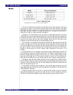
REFCLKM
Description
0
100 MHz reference clock input.
1
125 MHz reference clock input.
Table 2.1 Reference Clock Mode Encoding
Summary of Contents for 89HPES12N3
Page 10: ...IDT Table of Contents PES12N3 User Manual iv June 7 2006 Notes...
Page 14: ...IDT List of Figures PES12N3 User Manual viii June 7 2006 Notes...
Page 36: ...IDT Clocking Reset and Initialization Reset PES12N3 User Manual 2 8 June 7 2006 Notes...
Page 40: ...IDT Link Operation Slot Power Limit Support PES12N3 User Manual 3 4 June 7 2006 Notes...
Page 50: ...IDT Switch Operation Switch Core Errors PES12N3 User Manual 4 10 June 7 2006 Notes...
Page 54: ...IDT Power Management Active State Power Management PES12N3 User Manual 5 4 June 7 2006 Notes...
Page 62: ...IDT Hot Plug and Hot Swap Hot Swap PES12N3 User Manual 6 8 June 7 2006 Notes...
Page 78: ...IDT SMBus Interfaces Slave SMBus Interface PES12N3 User Manual 7 16 June 7 2006 Notes...
Page 148: ...IDT Test and Debug SerDes Test Clock PES12N3 User Manual 10 6 June 7 2006...
Page 158: ...IDT JTAG Boundary Scan Usage Considerations PES12N3 User Manual 11 10 June 7 2006 Notes...


