IDT Hot-Plug and Hot-Swap
Introduction
PES12N3 User Manual
6 - 3
June 7, 2006
Notes
The PCI Express® Base Specification revision 1.0a allowed a hot-plug attention indicator, power indi-
cator, and attention button to be located on the board on which the slot is implemented or on the add-in
board. When located on the add-in board, state changes are communicated between the hot-plug controller
associated with the slot and the add-in card via hot-plug messages. This capability was removed in revision
1.1 of the PCI Express Base Specification.
Therefore, there are differences in the behavior of a PCIe 1.0a hot-plug capable switch and a PCIe1.1
hot-plug capable switch. The Hot Plug Mode (HPMODE) bit in the upstream port’s Switch Control
(PA_SWCTL) register selects the operating mode of the hot-plug functionality in the PES12N3. Differences
in operation are noted in the following sections.
Hot-Plug with Downstream Port(s) Connected to a Slot
This section discusses the use of the PES12N3 in which one or both the of the downstream ports are
used in an application in which an add-in card may be hot-plugged into a downstream slot. Associated with
each downstream port in the PES12N3 is a hot-plug controller. The hot-plug controller may be enabled by
setting the HPC bit in the PCI Express Slot Capabilities (PCIESCAP) register during configuration (e.g., via
serial EEPROM).
The PES12N3 allows sensor inputs and indicator outputs to be located next to the slot or on the plug in
module. When implemented on the slot, the appropriate bits should be set during configuration in the PCI
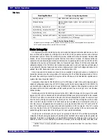
Express Slot Capabilities (PCIESCAP) register. Table 6.7 lists the hot-plug inputs and outputs that may be
associated with a slot. When enabled during configuration in the PCIESCAP register, these inputs and
outputs are made available to external logic using an external I/O expander located on the master SMBus
interface.
The PES12N3 only supports presence detect signalling via a pin assertion. It does not support in-band
presence detect.
Hot-Plug I/O Expander
The PES12N3 utilizes an external SMBus/I2C-bus I/O expander connected to the master SMBus inter-
face for hot-plug related signals associated with downstream ports. It is not possible to utilize EEPROM
commands to toggle the I/O expander outputs due to conflicting usage of the master SMBus. SMBus writes
or configuration writes can be used to control the I/O expander outputs.
The PES12N3 is designed to work with Phillips PCA9555 compatible I/O expanders. See the Phillips
PCA9555 data sheet for details on the operation of this device.
The external SMBus I/O expander provides 16 bit I/O pins that may be configured as inputs or outputs.
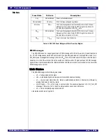
The mapping of downstream port B and C hot-plug signals listed in Table 6.7 to these I/O pins is exhibited
in Table 6.8.
Signal
Type
Name/Description
PxAPN
I
Port x
1
Attention Push button Input.
1.
x corresponds to downstream port B or C.
PxPDN
I
Port x Presence Detect Input.
PxPFN
I
Port x Power Fault Input.
PxMRLN
I
Port x Manually-operated Retention Latch (MRL) Input.
PxAIN
O
Port x Attention Indicator Output.
PxPIN
O
Port x Power Indicator Output.
PxPEP
O
Port x Power Enable Output.
PxINTERLOCKP
O
Port x Electromechanical Interlock.
Table 6.7 Downstream Ports B and C Hot Plug Signals
Summary of Contents for 89HPES12N3
Page 10: ...IDT Table of Contents PES12N3 User Manual iv June 7 2006 Notes...
Page 14: ...IDT List of Figures PES12N3 User Manual viii June 7 2006 Notes...
Page 36: ...IDT Clocking Reset and Initialization Reset PES12N3 User Manual 2 8 June 7 2006 Notes...
Page 40: ...IDT Link Operation Slot Power Limit Support PES12N3 User Manual 3 4 June 7 2006 Notes...
Page 50: ...IDT Switch Operation Switch Core Errors PES12N3 User Manual 4 10 June 7 2006 Notes...
Page 54: ...IDT Power Management Active State Power Management PES12N3 User Manual 5 4 June 7 2006 Notes...
Page 62: ...IDT Hot Plug and Hot Swap Hot Swap PES12N3 User Manual 6 8 June 7 2006 Notes...
Page 78: ...IDT SMBus Interfaces Slave SMBus Interface PES12N3 User Manual 7 16 June 7 2006 Notes...
Page 148: ...IDT Test and Debug SerDes Test Clock PES12N3 User Manual 10 6 June 7 2006...
Page 158: ...IDT JTAG Boundary Scan Usage Considerations PES12N3 User Manual 11 10 June 7 2006 Notes...


