IDT Hot-Plug and Hot-Swap
Introduction
PES12N3 User Manual
6 - 4
June 7, 2006
Notes
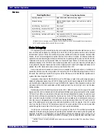
The port B and C electromechanical interlock outputs are only used in PCIe 1.1 mode (i.e., HPMODE bit
set). These signals are driven to their negated state in PCIe 1.0a mode.
During configuration of the PES12N3, the SMBus/I2C-bus address of the hot-plug I/O expander should
be written to the Hot-plug I/O Expander Master SMBus Address (IOEADDR) field in the SMBUS status
(PA_SMBUSSTS) register.
SMBus write transactions are issued to the I/O expander by the PES12N3 to configure the device when-
ever the value of the IOEADDR field is modified. Outputs for downstream ports that are disabled are set to
their negated value (e.g., the power indicator is turned off).
The I/O expander configuration sequence issued by the PES12N3 is as follows:
–
write value 0x50 to I/O expander register 2
–
write value 0x50 to I/O expander register 3
–
write value 0x0 to I/O expander register 4 (no inversion in IO-0)
–
write value 0x0 to I/O expander register 5 (no inversion in IO-1)
–
write value 0x0F to I/O expander register 6 (bits 4, 5, 6 and 7 are outputs of IO-0)
–
write value 0x0F to I/O expander register 7 (bits 4, 5, 6 and 7 are outputs of IO-1)
–
read value of I/O expander register 0 to obtain the current state of the I/O IO-0 inputs.
–
read value of I/O expander register 1 to obtain the current state of the I/O IO-I inputs.
Whenever a hot-plug output from port B or C needs to change state, a master SMBus transaction is initi-
ated to update the state of the I/O expander. This write operation causes the I/O expander to change the
state of its output(s). Port B output values are written to I/O expander register 2 and Port C values are
written to I/O expander register 3.
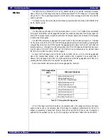
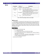
SMBus I/O
Expander
Bit
Type
Signal
0 (I/O-0.0)
1
1.
I/O-x.y corresponds to the notation used for PCA9555 port x I/O pin y.
I
PBAPN
1 (I/O-0.1)
I
PBPDN
2 (I/O-0.2)
I
PBPFN
3 (I/O-0.3)
I
PBMRLN
4 (I/O-0.4)
O
PBAIN
5 (I/O-0.5)
O
PBPIN
6 (I/O-0.6)
O
PBPEP
7 (I/O-0.7)
O
PBINTERLOCKP
2
2.
Not used in PCIe 1.0a mode (i.e., HPMODE bit cleared).
8 (I/O-1.0)
I
PCAPN
9 (I/O-1.1)
I
PCPDN
10 (I/O-1.2)
I
PCPFN
11 (I/O-1.3)
I
PCMRLN
12 (I/O-1.4)
O
PCAIN
13 (I/O-1.5)
O
PCPIN
14 (I/O-1.6)
O
PCPEP
15 (I/O-1.7)
O
PCINTERLOCKP
2
Table 6.8 SMBus I/O Expander Signals
Summary of Contents for 89HPES12N3
Page 10: ...IDT Table of Contents PES12N3 User Manual iv June 7 2006 Notes...
Page 14: ...IDT List of Figures PES12N3 User Manual viii June 7 2006 Notes...
Page 36: ...IDT Clocking Reset and Initialization Reset PES12N3 User Manual 2 8 June 7 2006 Notes...
Page 40: ...IDT Link Operation Slot Power Limit Support PES12N3 User Manual 3 4 June 7 2006 Notes...
Page 50: ...IDT Switch Operation Switch Core Errors PES12N3 User Manual 4 10 June 7 2006 Notes...
Page 54: ...IDT Power Management Active State Power Management PES12N3 User Manual 5 4 June 7 2006 Notes...
Page 62: ...IDT Hot Plug and Hot Swap Hot Swap PES12N3 User Manual 6 8 June 7 2006 Notes...
Page 78: ...IDT SMBus Interfaces Slave SMBus Interface PES12N3 User Manual 7 16 June 7 2006 Notes...
Page 148: ...IDT Test and Debug SerDes Test Clock PES12N3 User Manual 10 6 June 7 2006...
Page 158: ...IDT JTAG Boundary Scan Usage Considerations PES12N3 User Manual 11 10 June 7 2006 Notes...

