167
PowerSpan II User Manual
80A1010_MA001_09
Integrated Device Technology
www.idt.com
9.
Resets, Clocks and Power-up Options
This chapter describes the resets, clocks and power-up options implemented by PowerSpan II. The
following topics are discussed:
•
•
•
“Power-Up Options” on page 171
9.1
Reset
PowerSpan II has several inputs to its reset logic. It also has the capability of propagating the reset to
the other side of the bus.
9.1.1
Reset Pins
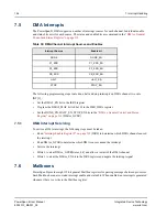
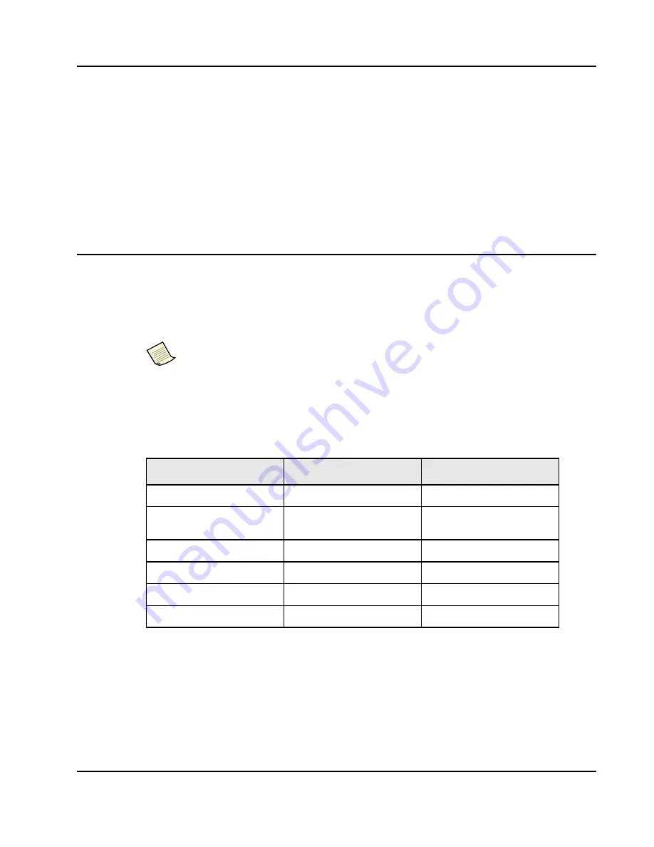
PowerSpan II reset pins are listed in
..
All pins indicate a reset condition when driven low, except for HEALTHY# signal.
9.1.1.1
Reset Direction Control Pins
Each bidirectional reset pin (PB_RST_, P1_RST#, and P2_RST#) has a dedicated direction control pin.
The assertion of a reset pin configured as input propagates to the other bus reset pins configured as
output.
PowerSpan II has reset capabilities for PCI Host, Adapter and Hot Swap applications
Table 42: PowerSpan II Reset Pins
Pin Name
Direction
Description
PO_RST_
Input only
Power-On Reset
HEALTHY#
Input only
Board Status (CompactPCI Hot
Swap)
PB_RST_
Bidirectional open drain
Processor Bus Hard Reset
P1_RST
#
Tristate bidirectional
PCI-1 Bus Reset
P2_RST
#
Tristate bidirectional
PCI-2 Bus Reset
TRST_
Input only
JTAG Reset


