9. Resets, Clocks and Power-up Options
171
PowerSpan II User Manual
80A1010_MA001_09
Integrated Device Technology
www.idt.com
9.3
Power-Up Options
To ensure proper operation, a number of PowerSpan II features must be configured by completion of
the power-up reset sequence. PowerSpan II has the following modes to configure these power-up
options:
•
Multiplexed System Pins mode
•
Configuration Slave mode (only available in a PowerQUICC II system)
The Multiplexed System Pins mode multiplexes several input pins during the power-up reset sequence
to configure power-up options. The Multiplexed System Pins mode is the default mode for PowerSpan
II.
In the Configuration Slave mode, the power-up options are latched from PB_D. PB_RSTCONF_ is
asserted by the configuration master during the assertion of PB_RST_. Refer to the
MPC8260
(PowerQUICC II) User Manual
for a detailed description of configuration master functionality.
Power-up option status can be confirmed by reading the Reset Control and Status (RST_CSR) register
(see
“Configuration Slave Mode” on page 175
for more information).
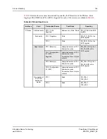
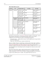
lists PowerSpan II power-up options and directions for their configuration with PowerSpan II
system pins and the processor data bus in configuration slave mode.
Power-up options are not affected by reset events on the PB_RST_, P1_RST# or P2_RST#
pins.
Table 45: PowerSpan II Power-up Options
Power-up Option
Selection
System Pin
a
PB_D Pin
b
RST_CSR Register
PB Arbiter Enable
(PWRUP_PB_ARB_EN)
Enable PB Arbiter
PB_FAST=1
PB_D[0]=1
PB_ARB_EN=1
Disable PB Arbiter
PB_FAST=0
PB_D[0]=0
PB_ARB_EN=0
PCI-1 Arbiter Enable
(PWRUP_P1_ARB_EN)
Enable
PCI-1 Arbiter
P1_M66EN=1
PB_D[1]=1
P1_ARB_EN=1
Disable
PCI-1 Arbiter
P1_M66EN=0
PB_D[1]=0
P1_ARB_EN=0
PCI-2 Arbiter Enable
(PWRUP_P2_ARB_EN)
Enable
PCI-2 Arbiter
P2_M66EN=1
PB_D[2]=1
P2_ARB_EN=1
Disable
PCI-2 Arbiter
P2_M66EN=0
PB_D[2]=0
P2_ARB_EN=0
Primary PCI Select
(PWRUP_PRI_PCI)
PCI-1 is Primary
INT[5]_=1
PB_D[3]=0
PRI_PCI=0
PCI-2 is Primary
INT[5]_=0
PB_D[3]=1
PRI_PCI=1

