235
PowerSpan II User Manual
80A1010_MA001_09
Integrated Device Technology
www.idt.com
12. Register
Descriptions
This chapter describes the registers used in PowerSpan II. It describes the register settings and bits
which enable PowerSpan II features and functionality. The following topics are discussed:
•
•
•
“Configuration and IACK Cycle Generation” on page 246
•
“Register Descriptions” on page 248
12.1
Register Access
The PowerSpan II registers can be accessed from both PCI and the processor bus. PowerSpan II allows
reads to its registers from all of its bus interfaces at the same time. However, writes may occur from
only one bus interface at a time.
12.1.1
Register Map
The 4 Kbytes of PowerSpan II Control and Status Registers (PCSR) are used for PCI Control and
Status Registers (CSRs), and for overall PowerSpan II operation. The PCSR space is functionally
divided into two areas: the PCI CSR space and the PowerSpan II PCSR space. PSCR space is
accessible from the Processor Bus, PCI-1 or PCI-2 interfaces.
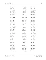
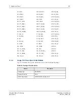
is a detailed memory map for PCSR space and shows the PowerSpan II register map for the
Dual PCI PowerSpan II. PowerSpan II is available as both the Single PCI PowerSpan II and Dual PCI
PowerSpan II.
The shaded registers under PCI-1 Configuration and PCI-2 Configuration registers exist only if the
associated PCI Interface is configured as the Primary Interface. A interface is configured as Primary
using a power-up option (see
“Resets, Clocks and Power-up Options” on page 167
for more
information). The PCI Interface that is designated as Primary has added functionality which includes
CompactPCI Hot Swap support, Vital Product Data support and an I
2
C Interface. Refer to
for more information on Primary Interface functionality.
Table 64: PowerSpan II Register Map
Offset
Register Mnemonic
See
PCI-1 Configuration Registers
0x000
P1_ID
“PCI-1 ID Register” on page 250
0x004
P1_CSR


