12. Register Descriptions
319
PowerSpan II User Manual
80A1010_MA001_09
Integrated Device Technology
www.idt.com
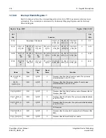
ELOAD_OPT[1:0]
R
G_RST
0
EEPROM
EEPROM load option
Identifies the load option selected in the first byte
of the power-up EEPROM.
00=do not load
01=short load
10=long load
11=reserved
P1_LOCKOUT
R/Write 1 to
Clear
G_RST
1
EEPROM
PCI-1 lockout
When set, all configuration and memory register
space accesses from PCI are retried. The
Px_LOCKOUT bit must be cleared for all memory
space accesses to the PowerSpan II’s PCI target
images.
0=not set
1=set
P2_LOCKOUT
R/Write 1 to
Clear
G_RST
1
EEPROM
PCI-2 lockout
When set, all configuration and memory register
space accesses from PCI are retried. The
Px_LOCKOUT bit must be cleared for all memory
space accesses to the PowerSpan II’s PCI target
images.
0=not set
1=set
Single PCI PowerSpan II: Reserved
PCI_ARB_CFG
Write 1 to set
G_RST
0
EEPROM
PCI Arbiter Pins Configured
When set, this bit enables recognition of external
master requests on PCI_REQ#[7:5] (see
)
0=Floating PCI Arbiter pins not yet configured
1=Floating PCI Arbiter pins configured
Single PCI PowerSpan II: Reserved
PCI_M7
R/W
G_RST
0
EEPROM
PCI Arbiter Master 7
0=PowerSpan II PCI-1 arbiter
1=PowerSpan II PCI-2 arbiter
Single PCI PowerSpan II: Reserved
PCI_M6
R/W
G_RST
0
EEPROM
PCI Arbiter Master 6
0=PowerSpan II PCI-1 arbiter
1=PowerSpan II PCI-2 arbiter
Single PCI PowerSpan II: Reserved
Name
Type
Reset
By
Reset
State
Function


