12. Register Descriptions
343
PowerSpan II User Manual
80A1010_MA001_09
Integrated Device Technology
www.idt.com
12.5.54
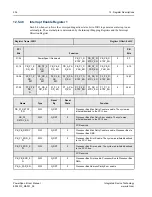
Interrupt Map Register PCI-2
This register assigns an interrupt output pin to the corresponding interrupt source. All sources are
associated with errors detected by the PCI-2 Interface.
defines the mapping
definitions.
This register is not implemented in the Single PCI PowerSpan II and must be treated as reserved.
Register Name: IMR_P2
Register Offset: 434
PCI
Bits
Function
PB
Bits
31-24
P2_P1_ERR_MAP
0
P2_PB_ERR_MAP
0
0-7
23-16
P2_P2_ERR_MAP
0
P2_A_PAR_MAP
0
8-15
15-08
P2_P1_RETRY_MAP
0
P2_PB_RETRY_MAP
0
16-23
07-00
P2_P2_RETRY_MAP
PowerSpan II Reserved
24-31
I
Name
Type
Reset
By
Reset
State
Function
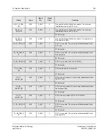
P2_P1_ERR[2:0]
R/W
G_RST
0
Map PCI-2 errors to an interrupt pin
P2_PB_ERR[2:0]
R/W
G_RST
0
Map PCI-2 errors to an interrupt pin
P2_P2_ERR_MAP[2:0]
R/W
G_RST
0
Map PCI-2 errors to an interrupt pin. PCI-2 to
PCI-2 DMA.
P2_A_PAR_MAP[2:0]
R/W
G_RST
0
Map PCI-2 address parity errors to an interrupt
pin
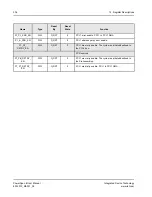
P2_P1_RETRY_MAP[2:0]
R/W
G_RST
0
Map PCI-2 max retry error to an interrupt pin
P2_PB_RETRY_MAP[2:0]
R/W
G_RST
0
Map PCI-2 max retry error to an interrupt pin
P2_P2_RETRY_MAP[2:0]
R/W
G_RST
0
Map PCI-2 max retry error to an interrupt pin.
PCI-2 to PCI-2 DMA.


