12. Register Descriptions
344
PowerSpan II User Manual
80A1010_MA001_09
Integrated Device Technology
www.idt.com
12.5.55
Interrupt Map Register Processor Bus
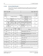
This register assigns an interrupt output pin to the corresponding interrupt source. All sources are
associated with errors detected by the Processor Bus Interface.
defines the
mapping definitions.
Register Name: IMR_PB
Register Offset: 0x438
PCI
Bits
Function
PB
Bits
31-24
PB_P1_ERR_MAP
0
PB_P2_ERR_MAP
0
0-7
23-16
PB_PB_ERR_MAP
0
PB_A_PAR_MAP
0
8-15
15-08
PB_P1_D_PAR_MAP
0
PB_P2_D_PAR_MAP
0
16-23
07-00
PB_PB_D_PAR_MAP
PowerSpan II Reserved
24-31
I
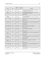
Name
Type
Reset
By
Reset
State
Function
PB_P1_ERR_MAP[2:0]
R/W
G_RST
0
Map Processor Bus error to an interrupt pin
PB_P2_ERR_MAP[2:0]
R/W
G_RST
0
Map Processor Bus error to an interrupt pin
2P: Reserved
PB_PB_ERR_MAP[2:0]
R/W
G_RST
0
Map Processor Bus error to an interrupt pin.
Processor Bus to Processor Bus DMA.
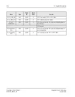
PB_A_PAR_MAP[2:0]
R/W
G_RST
0
Map Processor Bus address parity error to an
interrupt pin
PB_P1_D_PAR_MAP[2:0]
R/W
G_RST
0
Map Processor Bus data parity error to an
interrupt pin
PB_P2_D_PAR_MAP[2:0]
R/W
G_RST
0
Map Processor Bus data parity error to an
interrupt pin
2P: Reserved
PB_PB_D_PAR_MAP[2:0]
R/W
G_RST
0
Map Processor Bus data parity error to an
interrupt pin. Processor Bus to Processor Bus
DMA.


