15. AC Timing
396
PowerSpan II User Manual
80A1010_MA001_09
Integrated Device Technology
www.idt.com
15.2
Single PCI PowerSpan II Timing Parameters
The timing parameters specified in this document are guaranteed by design. Test conditions for timing
parameters in
are:
•
Commercial (C): 0ºC to 70ºC, 3.15 - 3.45V, 2.38 - 2.63V
•
Industrial (I): -40ºC to 85ºC, 3.15 - 3.45V, 2.38 - 2.63V
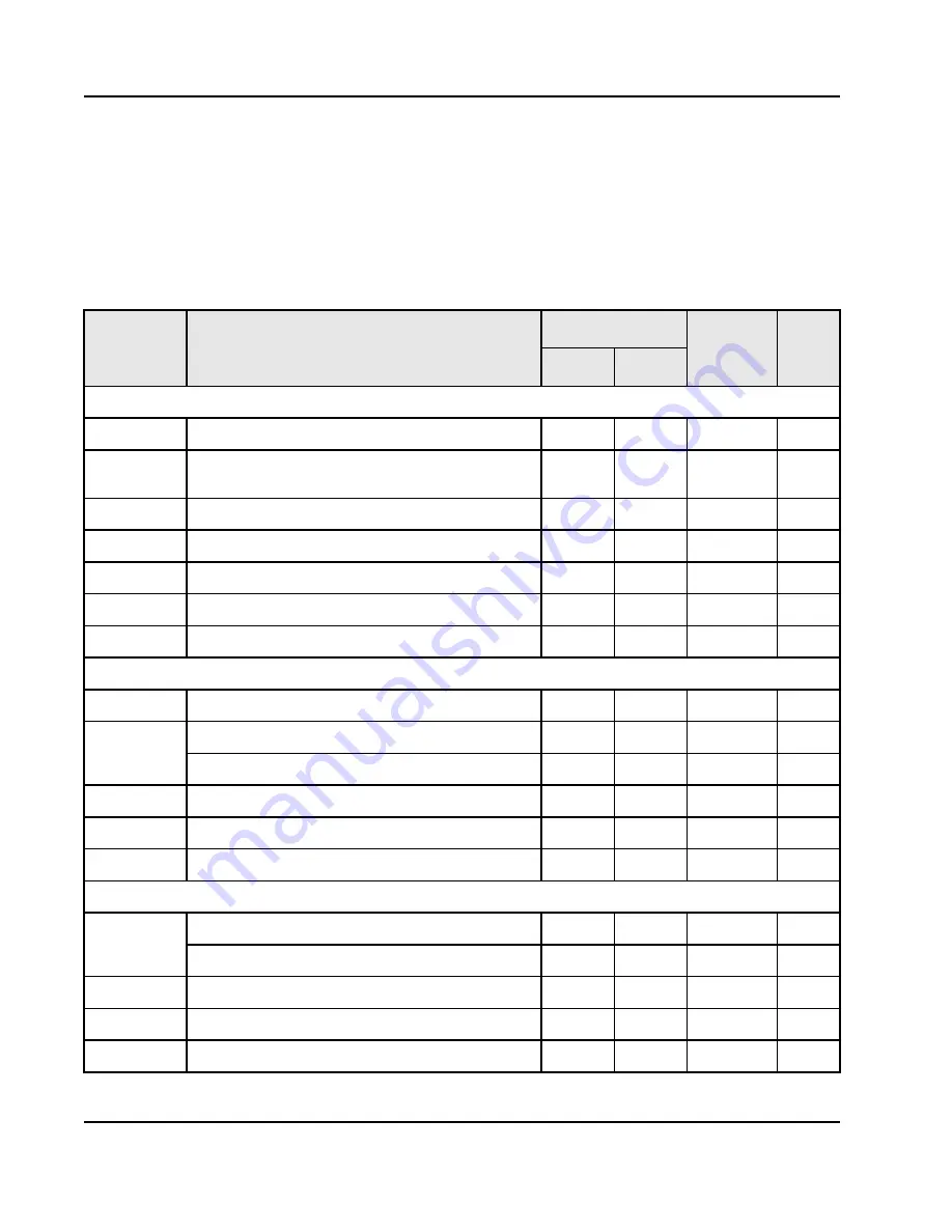
Table 97: Reset, and Clock Timing Parameters
Timing
Parameter
Description
CE/IE
Units
Note
Min
Max
Reset Timing
t
100
Power-up reset pulse width
500
ns
1
t
101
Back end power stable to back end power-up reset
released.
500
ns
t
102
Clock frequency stable before release of power-up reset
0
ns
2
t
103
PLL lock time
100
400
us
3
t
104
Reset propagation delay
20
ns
t
105
PCI bus reset timing after the negation of PO_RST_
50
ns
t
428
TRST_ pulse width
500
ns
4
Power-up Option Timing
t
110
Power-up option setup time on multiplexed system pins
10
ns
t
111
Power-up option hold time on multiplexed system pins
3.0
10
ns
5
INT[4]_ 3.2
10
ns
5
t
112
Power-up option setup time to PB_RSTCONF_
10
ns
t
113
Power-up option hold time from PB_RSTCONF_
5
ns
t
114
PB_RSTCONF_ pulse width
1
PB_CLKs
Processor Clock Timing
t
120
PB_CLK period
10
40
ns
PB_CLK frequency
25
100
MHz
t
121
PB_CLK high time
4
ns
t
122
PB_CLK low time
4
ns
t
123
PB_CLK slew rate
2
V/ns


