417
PowerSpan II User Manual
80A1010_MA001_09
Integrated Device Technology
www.idt.com
A. Hardware
Implementation
This chapter describes hardware implementation issues that can be faced when using the PowerSpan II
device. The following topics are discussed:
•
“Recommended Bootstrap Diode” on page 417
•
“PLL External Decoupling” on page 418
A.1
Overview
When PowerSpan II is designed into a system, certain hardware implementation requirements must be
addressed. This chapter deals with design issues in a PowerSpan II system.
A.2
Recommended Bootstrap Diode
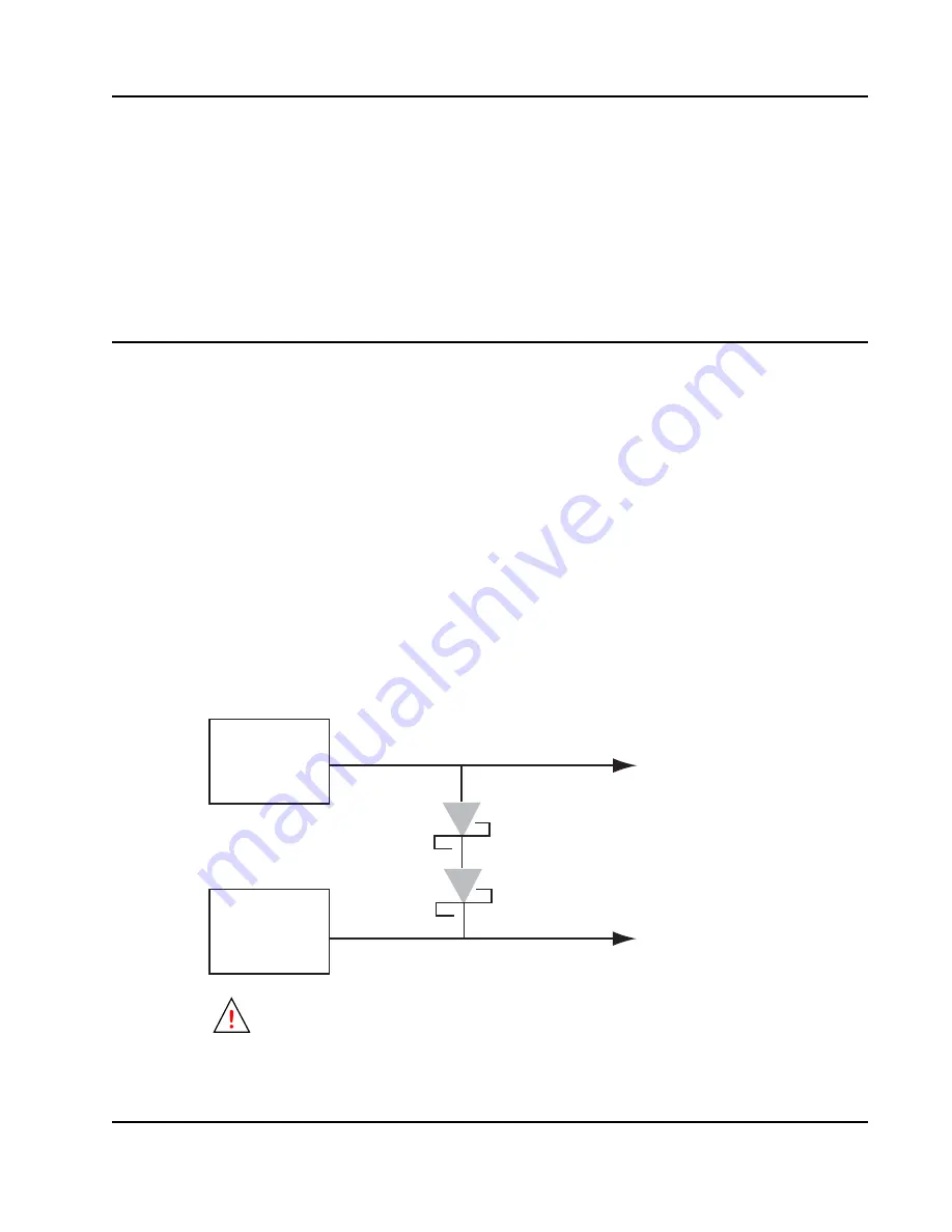
IDT recommends the use of a bootstrap diode between the power rails. The bootstrap diodes that are
used in the system must be configured so that a nominal Core Supply Voltage (Vdd Core) is sourced
from the I/O Supply Voltage (Vdd I/O) until the power supply is active. In
, two Schottky
barrier diodes are connected in series. Each of the diodes has a forward voltage (V
F
) of 0.6V at high
currents which provides a 1.2V current drop. This drop maintains 2.1V on the 2.5V power line. Once
the Core/PLL power supply stabilizes at 2.5V, the bootstrap diode(s) are reverse biased with small
leakage current.
Figure 40: Bootstrap Diodes for Power-up Sequencing
The forward voltage must be effective at the current levels required by PowerSpan II (< 1
amp). Do not use diodes with only a nominal V
F
which drops to low at high current.
I/O Power
Core/PLL
Power
3.3 V (Vdd I/O)
2.5 V (Vdd Core/Px_VDDA)


