2. PCI Interface
77
PowerSpan II User Manual
80A1010_MA001_09
Integrated Device Technology
www.idt.com
2.6.9
I
2
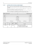
0 Outbound Post List Interrupt Status Register
The
I
2
0 2.0 Specification
requires the Outbound Post_List Interrupt Status register to be located at
offset 0x30 in the
Memory
region specified by the first base address register (I
2
0 Base Address Register
- Px_BSI2O).
When the I
2
0 messaging unit in PowerSpan II is enabled (I2O_CSR[I2O_EN] = 1), a Memory access
from PCI to offset 0x30 from Px_BSI2O is destined for OPL_IS.
When the I
2
0 messaging unit in PowerSpan II is not enabled, the OPL_IS register is not visible to read
or write access. The register essentially disappears from all PowerSpan II memory maps.
Register Name: OPL_IS
Register Offset: 030
PCI
Bits
Function
PPC
Bits
31-24
I
2
O Reserved
0-7
23-16
I
2
O Reserved
8-15
15-08
I
2
O Reserved
16-23
07-00
I
2
O Reserved
OPL_
ISR
I
2
O Reserved
24-31
Name
Type
Reset
By
Reset
State
Function
OPL_ISR
R
Px_RST
0
Outbound Post List Interrupt Service Request
0 = Outbound Post_List FIFO is empty
1 = Outbound Post_List FIFO is not empty. The value of the
interrupt mask bit does not affect this bit.


