127
PowerSpan II User Manual
80A1010_MA001_09
Integrated Device Technology
www.idt.com
5. I
2
C/EEPROM
The I
2
C (Inter-IC) bus is a bi-directional, two-wire serial data and serial clock bus that provides
communication links between integrated circuits (ICs) in an embedded application. Each device is
recognized by a unique address and can operate as either a receiver device (for example, an LCD
driver), or a transmitter device (for example, EEPROM) with the capability to both receive and send
information. Transmitters and receivers can operate in either master or slave mode, depending on
whether the IC initiates data transfers.
This chapter discusses the following topics about the PowerSpan II I
2
C/EEPROM Interface:
•
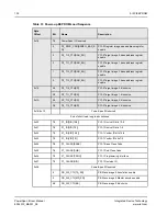
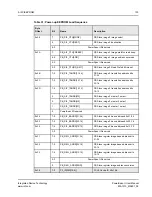
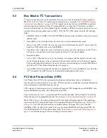
“Power-Up Configuration” on page 128
•
•
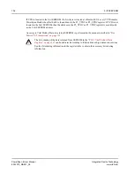
“PCI Vital Product Data (VPD)” on page 135
5.1
Overview
PowerSpan II has a master only, I
2
C bus compatible interface which supports up to eight I
2
C slave
devices. This interface is primarily used by PowerSpan II for the initialization of registers and for
reading and writing PCI Vital Product Data (VPD). However, PowerSpan II also provides a mechanism
for processor bus and PCI masters to access the I
2
C devices.
PowerSpan II I
2
C Interface supports the following features:
•
I
2
C 7-bit device addressing
•
Standard mode (up to 100 Kbits/s)
•
Single read/write (random read, byte write)
•
Sequential read during power-up configuration
The interface consists of two pins: I2C_SDA and I2C_SCLK. I2C_SDA is a bidirectional open drain
signal for transferring address, control, and data bits. I2C_SCLK is the clock output for the I
2
C slave
devices. I2C_SCL is derived from the processor bus clock. For example, at the maximum Processor
Bus Clock (PB_CLK) frequency of 100 MHz, the I2C_SCLK clock rate is 100 kHz.
PowerSpan II does not support multiple masters on the same I
2
C bus.

