7. Interrupt Handling
147
PowerSpan II User Manual
80A1010_MA001_09
Integrated Device Technology
www.idt.com
7.3
Interrupt Registers
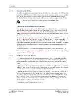
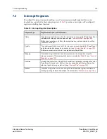
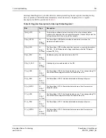
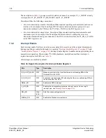
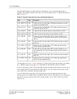
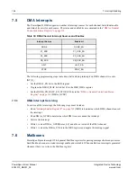
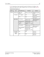
PowerSpan II interrupt status and enabling, as well as message passing through mailboxes and
doorbells are controlled by the interrupt registers.
provides a description of PowerSpan II
registers controlling these functions.
Table 33: Interrupt Register Description
Register Type
Register Description and Operation
Status
The status register bits cover all of the interrupt sources supported PowerSpan II and
indicate active interrupt sources when set (see
“Interrupt Status” on page 148
With a some exceptions, all bits in these registers are read and cleared by setting
(“R/Write 1 to Clear”)
Enable
The enable register bits cover all of the interrupt sources supported by PowerSpan II
and allow status bits to assert an external pin (see
“Interrupt Enable” on page 150
).
With some exceptions, all bits in these registers are Read/Write.
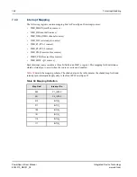
Mapping
This series of registers allow each interrupt source to be mapped to a specific
interrupt output pin. The mapping definitions are provided in
)
Direction
Interrupt Direction refers to the ability to control the input/output characteristics of the
PowerSpan II interrupt pins. Each pin has a corresponding bit that configures it as
either an input-only or an output-only (see
Mailbox
The Mailbox registers are a series of eight 32-bit Read/Write registers available for
message passing between PowerSpan II interfaces (see

