7. Interrupt Handling
150
PowerSpan II User Manual
80A1010_MA001_09
Integrated Device Technology
www.idt.com
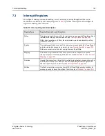
groups several bits under one name. For example, P1_x_RETRY actually
corresponds to P1_P2_RETRY, P1_PB_RETRY, and P1_P1_RETRY.
PowerSpan II has the following conventions:
•
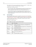
For errors detected by a master, PowerSpan II has separate reporting mechanisms for each source
interface. For example, if the PowerSpan II PCI-2 master detects an address parity error on a
transaction claimed by the PB slave, the P2_PB_A_PAR bit in the ISR1 register is set.
•
For errors detected by a target/slave, PowerSpan II has separate reporting mechanisms for each
destination port. For example, if the PowerSpan II PB slave detects a data parity error on a
transaction destined for an agent connected to the PCI-1 external interface, the P1_PB_A_PAR bit
in the ISR1 register is set.
7.3.2
Interrupt Enable
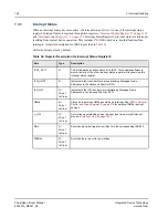
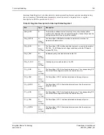
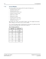
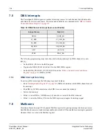
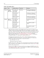
Each interrupt enable bit allows an active source status bit to assert one of the external interrupt pins.
Interrupt enabling is controlled through two registers:
“Interrupt Enable Register 0” on page 332
and
“Interrupt Status Register 1” on page 329
. Interrupt Enable Register 0 enables interrupts resulting from
normal device operation. This includes I
2
O, DMA, hardware, doorbell and mailbox interrupts. A
register description for IER0 is in
.
All interrupts are disabled by default.
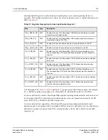
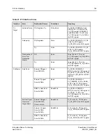
Table 36: Register Description for Interrupt Enable Register 0
Bits
Type
Description
I2O_HOST_MASK
R/W
Masks an interrupt to the Host that there are outstanding MFAs in the
Outbound Post List FIFO.
I2O_IOP_EN
R/W
Enables an interrupt to the IOP indicating that there are outstanding MFAs in
the Inbound Post List FIFO.
DMAx_EN
R/W
Enables the DMAx interrupt
x_HW_EN
R/W
Enables the corresponding hardware interrupt source t (one of eight
interrupt pins, see
DBx_EN
Write 1
to Set
Sets the corresponding status bit
MBOXx_EN
R/W
Enables the Mailbox interrupt source

