12. Register Descriptions
329
PowerSpan II User Manual
80A1010_MA001_09
Integrated Device Technology
www.idt.com
12.5.46
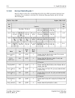
Interrupt Status Register 1
This register is one of two interrupt status registers. ISR1 is organized with error conditions in
PowerSpan II.
Register Name: ISR1
Register Offset: 0x414
PCI
Bits
Function
PB
Bits
31-24
ISR0_AC
TV
PowerSpan II Reserved
PB_P1_R
ETRY
PB_P2_R
ETRY
PB_PB_R
ETRY
0
0-7
23-16
PB_P1_E
RR
PB_P2_E
RR
PB_PB_E
RR
PB_A_PA
R
PB_P1_D
_PAR
PB_P2_D
_PAR
PB_PB_D
_PAR
0
8-15
15-08
P2_P1_E
RR
P2_PB_E
RR
P2_P2_E
RR
P2_A_
PAR
P2_P1_R
ETRY
P2_PB_R
ETRY
P2_P2_R
ETRY
0
16-23
07-00
P1_P2_E
RR
P1_PB_E
RR
P1_P1_E
RR
P1_A_PA
R
P1_P2_R
ETRY
P1_PB_R
ETRY
P1_P1_R
ETRY
0
24-31
Name
Type
Reset
By
Reset
State
Function
ISR0_ACTV
R
G_RST
0
Indicates an interrupt status bit is set in ISR0 register.
This bit is a logical OR of all the status bits in the ISR0
register. If any register is set, ISR0_ACTV is set. When all
bits of the ISR0 register are cleared, ISR0_ACTV is cleared.
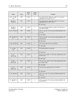
PB_P1_
RETRY
R/Write 1 to
Clear
G_RST
0
Processor Bus Max Retry Error. Maximum number of retries
detected. The cycle was initiated/destined to the PCI 1 bus.
PB_P2_
RETRY
R/Write 1 to
Clear
G_RST
0
Processor Bus Max Retry Error. Maximum number of retries
detected. The cycle was initiated/destined to the PCI-2 bus.
Single PCI PowerSpan II: Reserved
PB_PB_RETRY
R/Write 1 to
Clear
G_RST
0
Processor Bus Max Retry Error. Maximum number of retries
detected during Processor Bus to Processor Bus DMA.
PB_P1_ERR
R/Write 1 to
Clear
G_RST
0
Processor Bus interface asserted/received PB_TEA_. The
cycle was initiated/destined to the PCI-1 bus.
PB_P2_ERR
R/Write 1 to
Clear
G_RST
0
Processor Bus interface asserted/received PB_TEA_. The
cycle was initiated/destined to the PCI-2 bus.
Single PCI PowerSpan II: Reserved
PB_PB_ERR
R/Write 1 to
Clear
G_RST
0
Processor Bus interface asserted/received PB_TEA_ during
Processor Bus to Processor Bus DMA.


