3. Processor Bus Interface
91
PowerSpan II User Manual
80A1010_MA001_09
Integrated Device Technology
www.idt.com
3.3.1.5
Address Parity
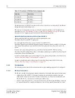
Address parity checking is provided on each byte of the address bus. Address parity bit assignments are
defined in
.
When the PB Slave detects an address parity error during its decode process it does not assert Address
Acknowledge (PB_AACK_). Address parity checking is enabled with the Address Parity Enable
(AP_EN) bit in the
“Processor Bus Miscellaneous Control and Status Register” on page 304
. Odd
parity versus even parity is configured with the PARITY bit in the same register.
Special Parity Requirements with the PowerQUICC II
Address parity and data parity must be specially programmed in a joint
PowerSpan II and PowerQUICC II application.
In a joint application all memory accesses from the PowerQUICC II to PowerSpan II must be routed
through the internal memory controller on the PowerQUICC II. When the data is passed through the
memory controller both address parity and data parity can be used in the system.
If accesses do not pass through the memory controller of the PowerQUICC II before reaching
PowerSpan II, and PowerSpan II has either or both address and data parity enabled, then PowerSpan II
reports parity errors on the transaction.
To enable or disable address parity in PowerSpan II, set the Address Parity Enable (AP_EN) bit in the
“Processor Bus Miscellaneous Control and Status Register” on page 304
To enable or disable data parity in PowerSpan II, set the Data Parity Enable (AP_EN) bit in the
“Processor Bus Miscellaneous Control and Status Register” on page 304
Table 15: PowerSpan II PB Address Parity Assignments
Address Bus
Address Parity
PB_A[0:7]
PB_AP[0]
PB_A[8:15]
PB_AP[1]
PB_A[16:23]
PB_AP[2]
PB_A[24:31]
PB_AP[3]

