background image


ViVOpayKiosk III UserManual 


Page12 of 18


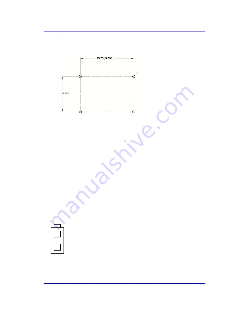
63.50 [ 2.500 

]

2.  Locate the four 4.4mm (0.173 inch) mounting holes by holding the ViVOpay Kiosk III 

Controller in position and mark the holes. The following diagram shows the spacing on the 
holes to be drilled for mounting the ViVOpay Kiosk III Controller. 


3.  Drill the four 4.4 mm (0.173) mounting holes using a number 17 drill bit. 

4.  Use four screws and nuts to mount the ViVOpay Kiosk III Controller to the kiosk surface. 

(Mounting screws are not provided and must be supplied by the installer.) 

5.  Tighten the nuts to hold the ViVOpay Kiosk III Controller in position so that it does not move. 


2.3.2


Mounting


the


ViVOpay


Kiosk


III


Controller


Using


Mounting


Tape


1.  Position the ViVOpay Kiosk III Controller on the interior of the kiosk making sure that there 

is sufficient room for the antenna mounting surface to be fully opened. 

2.  Attach double-sided tape to the mounting surface. 

3.  Position the ViVOpay Kiosk III Controller over the mounting tape and gently apply 

pressure to hold the controller in position. 


2.4


Connecting


to


Power


The KIOSK III can be powered through the serial communications port or the two-socket power 
connector. If you are using USB data communications, you must power the KIOSK III though the 
two-socket power connector. 
 
C7.5 to 45VDC to the white two-socket Molex connector (mating connector Molex P/N 
0039012020 with 5556-series crimps) or to pins 1 and 2 of the RS-232 connector (see next section). 


Pin 1 - +7.5v to 45VDC

Pin 2 - Ground 

Summary of Contents for Kiosk III

Page 1: ...User Manual Kiosk III 80136500 001 Copyright...

Page 2: ...recorded or any other method or translated into another language or language form without the express written consent of ID TECH ID TECH is a registered trademark of International Technologies and Sy...

Page 3: ...adio TV technician for help Changes or modifications to the ViVOpay Kiosk III not expressly approved by ViVOtech could void the user s authority to operate the ViVOpay Kiosk III IC Compliance Warning...

Page 4: ...osk III Controller 11 2 3 1 Mounting the ViVOpay Kiosk III Controller Using Screws 11 2 3 2 Mounting the ViVOpay Kiosk III Controller Using Mounting Tape 12 2 4 Connecting to Power 12 2 5 Connecting t...

Page 5: ...can besupplied via a single cable toreducing the effort and complexity of installation 1 1 Features Supports ISO 14443 Type A Type B and optional Type C Felica Supports ISO 18092 with protocol stacks...

Page 6: ...O 18092 Typical Read Range 4 6 cm 1 5 to 2 3 inches Physical Controller Height 105 mm 4 13 inches Width 76 2 mm 3 00 inches Depth 22 5 mm 0 88 inches Square Bezel Antenna Height 75 mm 2 95 inches Widt...

Page 7: ...Temperature 10 C to 50 C 14 F to 122 F duration 3 months Transit 40 C to 60 C 40 F to 160 F duration 1 week Operating Humidity 5 to 90 non condensing Storage Humidity 10 to 90 non condensing duration...

Page 8: ...fy that you have the following hardware for the installation of the ViVOpayKiosk III ViVOpay Kiosk III Controller ViVOpay Kiosk III Antenna either square or angle bezel Antenna LED power and data cabl...

Page 9: ...locate and mark the four 4 4mm 0 173 inch mounting holes 2 Using the Drill Template locate and mark the two 14 0 mm 0 551 inches access holes used for connecting the antenna power and the LED power a...

Page 10: ...kiosk Make sure to tighten the nuts securely so that the ViVOpay Kiosk III does not move on the outside surface of the kiosk If you are installing the Angle Bezel Antenna tighten the nuts to 5 7 in l...

Page 11: ...llation 2 3 Mounting the ViVOpay Kiosk III Controller Note The ViVOpay Kiosk III Controller must be mounted within 1 meter of the antenna If the antenna is mounted of a surface that opens such as a do...

Page 12: ...VOpay Kiosk III Controller Using Mounting Tape 1 Position the ViVOpay Kiosk III Controller on the interior of the kiosk making sure that there is sufficient room for the antenna mounting surface to be...

Page 13: ...er ground 4 7 5v to 45VDC 5 No connection 6 Reserved 7 Reserved 8 Reserved 9 Signal ground 10 Signal ground 11 RS 232 Tx 12 RS 232 Rx 13 No connection 14 Reserved To build your own RS 232 cable use Mo...

Page 14: ...has been entered on the kiosk control panel the customer should present their card fob phone in close proximity so that maximum surface area is parallel to the antenna A single beep and all four LEDs...

Page 15: ...erference come from A Radio frequency interference RFI can originate from a wide number of sources at the point of sale POS Some examples of sources of RF energy and RF interference include AM FM radi...

Page 16: ...t polarity is observed For more information refer to the Input Voltage under the Electrical specification section Replace the ViVOpay Kiosk III Reading Cards Fobs Phones LEDs do not light and beeper i...

Page 17: ...e The Kiosk III can be upgraded using either the serial or USB interfaces 6 1 Preparation To update the new firmware you will need PC with available serial or USB port Kiosk III with a serial data cab...

Page 18: ...of 18 6 Press the button Load to load the firmware on the reader the progress will be displayed 7 Disconnect power and the serial dongle if connected 8 Connect power to the Kiosk III and connect the s...

Reviews: