background image


Page | 10  


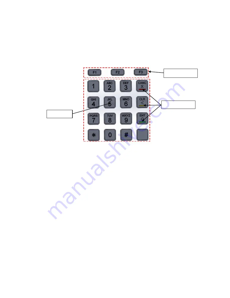
Tactile dot 

Color bar 

Function keys 

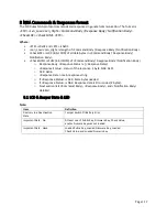
5.1.4


Keys 

Color:

 Silver gray Finish: Brushed finish 

Layout:

 Alphabetical characters printed on the keys 

Operation keys have engraved, colored bar and symbols:

 Cancel (red), Clear (yellow), Enter (green). 

3 Function Keys

 are etched or engraved with “F1” “F2” and “F3” respectively Tactile identifier on the 

numeral key 5. 

Meets ADA standard (which requires embossed symbols to be between 0.6 and 0.9 mm in height). 


5.2


Size & weight 

Size:

 107.5 mm *140 mm *29 mm  

Weight:

 526 g 

5.3


Mounting 

Use the provided cutouts to mount the device using standard #10 screws or equivalent (shaft diameter 5 

mm or 0.19 inch).  


Note: 

The head of the screw should be greater than 11 mm, less than 13 mm. For best results, use a 

washer (with outside diameter greater than 0.43 in. or 11 mm, less than 0.5 in. or 13 mm) under the 

screw head. 


Summary of Contents for SmartPIN L100

Page 1: ...ID TECH 10721 Walker Street Cypress CA 90630 Voice 714 761 6368 Fax 714 761 8880 80141505 001 User Manual SmartPIN L100 Rev H 25 March 2021 ...

Page 2: ...or corporation is authorized to assume for ID TECH any other liabilities in connection with the sales of any product In no event shall ID TECH be liable for any special incidental or consequential damages to purchaser or any third party caused by any defective item of equipment whether that defect is warranted against or not Purchaser s sole and exclusive remedy for defective equipment which does ...

Page 3: ... Reliability Environmental 15 6 3 1 Electro Static Discharges ESD 15 6 3 1 Environmental Temperature Range 15 6 4 Agency Certifications 15 7 BASE FUNCTIONALITY 16 7 1 PIN Pad function 16 7 2 Interface function 16 7 3 Key injection function 16 7 4 Low Power Modes 16 7 4 1 Sleep Mode 16 7 4 2 Stop Mode 20 µA 16 7 4 3 Bootloader function 16 8 NGA COMMANDS RESPONSES FORMAT 17 8 1 LCD Beeper State LED ...

Page 4: ... PIN 40 8 9 2 Get Numeric with Display Message 41 8 9 3 DisplayMessage and Get Numeric Key 42 8 9 4 DisplayMessage and Get Amount 42 8 9 5 Get Function Key 43 8 9 6 Cancel Command 43 8 9 7 Beeper Control 44 8 9 8 Set PIN Len 45 8 9 9 Get PIN Len 45 8 9 10 Set Numeric Len 45 8 9 11 Get Numeric Len 46 8 9 12 Default PINpad Group All Setting 46 8 9 13 Review PINpad Group All Setting 46 8 9 14 Manual ...

Page 5: ...t Signal 64 11 6 Display and Get Key command only between CR PINPAD 64 11 7 Get PIN command only between CR PINPAD 66 11 7 1 Plain text of Truncated Primary Account Number PAN pack 68 11 7 2 Plain text of PIN Block 68 11 8 Symmetric Key loading 68 11 8 1 3B Set Key Master and Working Key Description 68 11 8 2 3C Set Working Key 70 12 APPENDIX B OPOS JPOS 72 12 1 1 Methods Properties and Events 72 ...

Page 6: ... ask your ID TECH representative about the ID TECH Universal SDK for L100 Windows which contains libraries DLLs C source code a demo app and documentation for a C API on Windows By using the Universal SDK which also works with other ID TECH products such as the Spectrum Pro insert reader you can save time developing host applications that talk to the L100 via USB or RS 232 and take advantage of ma...

Page 7: ...version can work either as two standalone products or be paired together no special CA certification download required Supports multiple key slots using the same key storage hardware and firmware designin Spectrum Pro which can store fifteen 15 DUKPT keys and twelve 12 2048 bit RSA public keys as X 509 certificates Encrypted text and clear text entry RoHS and REACH compliant One year manufacturer ...

Page 8: ...ith local Application Software for controlling connected SmartPAY terminals IEC International Electrical Congress ISO International Organization for Standardization JPOS Java for Retail Point of Sale KSN Key Serial Number LCD Liquid Crystal Display mA MilliAmperes MAC Message Authentication Code MK SK Master Key Secession Key Key management MTBF Mean Time Between Failures mV MilliVolts OPOS OLE fo...

Page 9: ...r this means there are 4 20 128 or 10 240 dots in the LCD 5 1 3 LED There is one tri color red yellow green LED on the back of the L100 to display unit status Looking at the back of the L100 with the top LCD end up the LED is just to the left of the DB 9 connector opening Any given color of LED light can have multiple meanings depending on the context for details see the table under LCD Beeper Sta...

Page 10: ...le identifier on the numeral key 5 Meets ADA standard which requires embossed symbols to be between 0 6 and 0 9 mm in height 5 2 Size weight Size 107 5 mm 140 mm 29 mm Weight 526 g 5 3 Mounting Use the provided cutouts to mount the device using standard 10 screws or equivalent shaft diameter 5 mm or 0 19 inch Note The head of the screw should be greater than 11 mm less than 13 mm For best results ...

Page 11: ...Page 11 5 3 1 L100 Dimensions ...

Page 12: ...Page 12 5 4 Tamper Detection Tamper detect Use screw with shaft diam d such that 6 mm d 5 mm and head diam D such that 13 mm D 11 mm ...

Page 13: ... to do this before powering up the unit Conversely power down the unit before releasing tension on the nubs Note to close the tamper removal switch 1 63mm of displacement compression is required or 0 056kg of force but it is recommended that when using a M4 M5 hex nut to mount the unit a torque between 1 0 1 2 N m be applied to allow the gasket to prevent water ingress as well 5 2 Drop Test The L1...

Page 14: ...he front face is impact resistant to meet IK9 rating 10 joules of impact energy equivalent to dropping a 5kg object from 20 cm height 5 6 Key Life The L100 is designed for a minimum of 2 000 000 keystroke operations per key ...

Page 15: ...ipherals is cut off and wakes up by key press and communication from PC 6 3 Reliability Environmental MTBF 425010 hrs FR 2352 FITs BasicR 0 979 FR is failure rate FITs is failures per billion hours MTBF is the Mean Time between Failures in hours BasicR Reliability is the probability that the circuit taken as a purely Serial configuration will operate without failure for the mission time For exampl...

Page 16: ...for PIN Key Injection Can communicate with HSM using the key injection protocol for unattended products 7 4 Low Power Modes 7 4 1 Sleep Mode While using the RS232 interface Sleep Mode is controlled by a timeout after the L100 is idle for a specified time default is 120s While using the USB interface Sleep Mode is controlled by the USB suspend and resume signals Sleep Mode is used for battery opera...

Page 17: ... Notification Body o Response Body Response Status Response Data o Response Status status of the response 1 byte NAK 0x15 o ACK 0x06 o Response Data main response string o If Response Status is ACK More bytes needed o If Response Status is NAK Response data is Error codes 2 bytes o Next section lists Command Body Response Body and Notification Body detailed 8 1 LCD Beeper State LED Note Item Defin...

Page 18: ...y No DUKPT Key or Master Key Ready Not beeping If user passwords not set Blink Yellow If user passwords set or if legally in Removal State Steady Yellow If legally in Install State Steady Green Load Key State Activation PK FK CV NK and DTV loaded successfully Unit prepared to load DUKPT Key or Master Key Refer to XX DUKPT Key Loading Master Key Loading Refer to Key Loading Note If user passwords n...

Page 19: ...ne2 xxxxxxxx Line3 xxxxxxxx The Message and Plaintext Numeric Display is defined by Command Get Numeric Line0 xxxxxxxx Line1 xxxxxxxx Line2 xxxxxxxx Line3 The Message and Star Display is defined by Command Suspend Line0 SUSPEND Line1 PWD ERR Removal Detection Password Error 3 times continuously Modify default password Please input one password Please input new password Please input new password ag...

Page 20: ... F3 1 2 3 Cancel 4 5 6 Backspace 7 8 9 Enter 0 Blank 8 2 Tamper and Failed Self Check Indicators The SmartPIN L100 displays the following indicators when it has been tampered or has any of the other following internal issues such as an expired certificate missing key or similar fault discovered during a self check Indicator Tampered Status Other Issue Status Diagnostic LED Solid red Solid red LCD ...

Page 21: ... to safely take the device into and out of the activated removal detection state The first step is to set the device s user passwords Part 1 Setting User Activation Deactivation Password The SmartPIN L100 comes with two default Removal Detection passwords that need to be reset with user generated passwords before activating the Removal Detection feature If two user activation passwords have alread...

Page 22: ... seconds Any key will have a short tone to indicate entry Part 3 Activate Removal Detection To activate removal detection 1 Power on the L100 and immediately after the device beeps once and the LCD screen displays its version message press Cancel Clear Enter Blank Clear and Enter 6 keys Note the interval between keys cannot exceed 5 seconds 2 Enter password 1 which was set in Part 1 Setting User A...

Page 23: ...er enters an incorrect User Activation Password three times the device will beep its Invalid Tone and suspend for three minutes After the suspension ends the device quits the Want Fix Removal Device state Interval limits The interval between Password 1 and Password 2 cannot be more than 2 Minutes The interval between the two keys of a password cannot be more than 10 Seconds ...

Page 24: ...l Device state If the user enters an incorrect User Activation Password the device will beep short tone twice pause short tone once and then user need to re enter password If the user enters an incorrect User Activation Password three times the device will beep short tone twice pause short tone once and suspend for three minutes After the suspension ends the device quits the Want Fix Removal Devic...

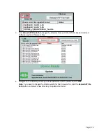
Page 25: ...eader Bootload Software app loads firmware files 4 Navigate to the directory where you downloaded the L100 firmware and click OK Note If you need to change the directory path for the firmware file click the Reload APP File Path button and select a new directory to update the file list ...

Page 26: ...Page 26 5 Select the firmware to load onto the L100 6 Click the Update button The ID TECH Reader Bootload Software app will update the L100 with the selected firmware ...

Page 27: ...are to update 8 The ID TECH Reader Bootload Software app displays a status bar for update progress 9 When the update completes the L100 will reboot and the ID TECH Reader Bootload Software app displays a Completed status and Application Update Succeeded ...

Page 28: ...gin contact your ID TECH representative to receive the most recent L100 firmware Download the ZIP file and extract it to your computer 1 Connect the L100 to your PC via either USB or serial port 2 Download and install the latest USDK Demo from the ID TECH Knowledge Base if you cannot access the link please contact support 3 Open the USDK demo from the Windows Start menu ...

Page 29: ...to and select the L100 firmware you downloaded earlier and click Open 6 The L100 will reboot and enter the bootloader at which point the SDK demo begins updating the device 7 When the firmware update completes the L100 will reboot again and the USDK demo will prompt Firmware Update Successful ...

Page 30: ...one data block continuously fails three times the L100 erases all applications and responds NAK with an error code then waits for the first data block in the Bootloader state If the Bootloader times out 30 seconds and if the application is not modified the L100 returns to the old application otherwise the L100 erases all applications and exist in the Bootloader state 8 6 1 Enter into Bootloader Co...

Page 31: ... is a random number Encrypted PAN Encryption Key Array is encrypted by Pairing DUKPT Key Step 2 The host passes the MAC to the PIN Pad Command Body 75 46 10 01 20 bytes ASCII KSN 6 bytes ASCII MAC Command Example STX Len Low Len High Command Body LRC CHK SUM ETX 02 00 75 46 10 01 20 bytes ASCII KSN 6 bytes ASCII MAC 03 Response Body 06 Verify OK PIN pad device save the new PAN Encryption Key or 15...

Page 32: ...re Version Number Return Hex String Response Body 06 K21Version Number 0x0D MAXQ firmware version 8 8 3 Enter into Bootloader Command Example STX Len Low Len High Command Body LRC CHK SUM ETX 02 03 00 78 46 7A 49 52 46 57 00 00 00 00 00 00 00 00 4E 70 03 Output Hex String Command Body 78 46 7A 49 52 46 57 Response Body 06 Device has the function or 15 Device does not have the function 8 8 4 Get Se...

Page 33: ...onse Body LRC CHK SUM ETX 02 0B 00 06 10 digit serial number 03 Response Hex String 020b000636313654353638393432673903 STX len low len high ACK 10 byte serial number LRC SUM STX The LRC and SUM will obviously depend on the model number ...

Page 34: ...el number LRC SUM STX In this example the model number is IDPB 602400M 8 8 7 Reset Warm reboot Command Body 78 46 49 Command Example STX Len Low Len High Command Body LRC CHK SUM ETX 02 03 00 78 46 49 77 07 03 Output Hex String 020300784649770703 Response Body 06 and LRC and SUM are 06 Note Device will Reset restart warm reboot after it responds ACK This is the Highest Priority Command in device e...

Page 35: ...nL LenH KeyStatusBlock format is Key Index and Key Name key slot key status Key Name Key Index and Key Name Host PINPAD Master DUKPT Key 0x00 PIN DUKPT Key 0x01 PIN Pairing DUKPT Key 0x03 Data Pairing DUKPT Key 0x04 CR PINPAD Master DUKPT Key 0x06 CR PINPAD MAC DUKPT Key 0x07 PIN Master Key 0x08 Pairing MSR BDK Key 0x0D LCL KEK HSM DUKPT KEY HSM DUKPT KEY 0x14 PIN Session Key 0x28 keyslot 2 bytes ...

Page 36: ...one 1 Exist 0xFF STOP Does not support this key Always 0 RKI KEK Admin DUKPT Key 0 None 1 Exist 0xFF STOP If the L100 has not been key injected response looks like 02070006000000000000060603 8 8 10 Set Remote Key Injection Timeout Command Body 78 53 01 01 02 Timeout_H Timeout_L Command Example STX Len Low Len High Command Body LRC CHK SUM ETX 02 07 00 78 53 01 01 02 00 C0 E9 8F 03 Output Hex Strin...

Page 37: ...0x00C0 192 seconds 8 8 12 Set Date Time Command Body 78 53 01 50 06 Date Time Command Example STX Len Low Len High Command Body LRC CHK SUM ETX 02 0B 00 78 53 01 50 06 39 F3 03 Output Hex String example 020b00785301500616052010305639f303 Where Data Time is 6 bytes data Year Month Date Hour Minute Second Item Value Area BCD Code Year 00 99 Month 01 12 Date 01 31 Hour 00 23 Minute 00 59 Second 00 59...

Page 38: ...portant Data State Activation IDLE State 8 8 14 Get All Fix Removal Records Command Body 78 52 01 51 Command Example STX Len Low Len High Command Body LRC CHK SUM ETX 02 04 00 78 52 01 51 7A 1C 03 Output Hex String 020400785201517A1C03 Response Body 06 Fix Removal Records Number Record Block Illegal Removal Records Number Record Block Where Fix Removal Records Number is Number of Fix Removal Recor...

Page 39: ...gnosis mode Get PIN Get Numeric Get Function Key Get PIN for Pro Display and Get Key for Pro and Active PINpad Activate Deactivate Passwords load cert load key and load important data for PINpad mode 8 8 16 Set Enter Sleep Mode Time Enter Sleep Mode timeout period the period after which the L100 if idle goes to sleep default is 120 seconds Command Body 78 46 71 TimeH TimeL Command Example STX Len ...

Page 40: ... len 1 byte The length of LCD Command format LCD Command format 1 20 bytes ASCII code Display Message Response Body 1 0x06 if operation is successful or 0x15 Error Code if it is not successful 2 Waiting for entering PIN And If Get Encrypted PIN with DUKPT Key under Triple DES 06 20 ASCII code KSN 16 ASCII code Encrypted PIN block If Get Encrypted PIN with MKSK 06 16 ASCII code Encrypted PIN block ...

Page 41: ...f Line2 0 While you press numeric key Device will increase the display space devoted to this numeric on LCD if Total numeric length is smaller than 16 While you press Backspace key Device will decrease the display space devoted to the last numeric on LCD if Total numeric length is not 0 1 While you press numeric key Device will increase display on LCD if Total numeric length is smaller than 16 Whi...

Page 42: ...e len LCD Message Data Response Body 1 0x06 if operation is successful or 0x15 Error Code if it is not successful 2 Waiting for entering Numeric And 06 len keys0 keys1 keys16 For example enter into 7 numeric keys 2 5 7 8 9 0 6 response is 06 07 25 78 90 6F FF FF FF FF FF FF FF FF FF FF FF FF Note Wait 30 Seconds The Numeric Len is 1 16 Per 10 Seconds if the Numeric length was not 0 the Numeric wou...

Page 43: ...If Enter 2 numeric 12 0 12 o If Enter 15 numeric 12345678901245 1234567890123 45 While you press Backspace key Device will decrease display numeric on LCD if Total numeric length is not 0 While you press Cancel key Device will display cursor on LCD if Total numeric length is not 0 or Device will quit the work state While Cancel Command was sent Device will quit the work state 8 9 5 Get Function Ke...

Page 44: ...t and second nibble for the second byte of Frequency If the Frequency is 1000 0x03E8 Fre1 Fre2 Fre3 Fre4 will be 0x45 0x38 0x30 0x33 According to the datasheet of Beeper of SmartPIN C100 Frequency will be more than 1000Hz and less than 20000Hz 4000Hz tone will generate the First Max Decibels sound 6000Hz tone will generate the Second Max Decibels sound Dur1 Dur2 is the first and second nibble for ...

Page 45: ...IN Len Command Body 75 52 01 01 Command Example STX Len Low Len High Command Body LRC CHK SUM ETX 02 04 00 75 52 01 01 27 C9 03 Output Hex String 0204007552010127C903 Response Body 06 75 01 01 02 MinLen MaxLen 8 9 10 Set Numeric Len Command Body 75 53 01 02 02 MinLen MaxLen Command Example STX Len Low Len High Command Body LRC CHK SUM ETX 02 07 00 75 52 01 02 02 MinLen MaxLen 3E E4 03 Output Hex S...

Page 46: ...and Body LRC CHK SUM ETX 02 03 00 75 53 00 26 C8 03 Output Hex String 02030075530026C803 Response Body 06 Below Setting should be reset to default value Function Name Default Value PIN Length Min is 4 Max is12 Numeric Length Min is 1 Max is16 8 9 13 Review PINpad Group All Setting Command Body 75 52 00 Command Example STX Len Low Len High Command Body LRC CHK SUM ETX 02 03 00 75 52 00 27 C7 03 Out...

Page 47: ...es Enter after entering CVV data due to command parameters the L100 outputs Enter Address and waits for the user to enter ADR data The data length is 0 or 20 and output in plaintext The user can also press Enter to go on to the next step if no data is entered If the user presses Enter after entering ADR data due to command parameters the L100 outputs Enter ZIP code and waits for the user to enter ...

Page 48: ...pted pin block when enter key is pressed 1 When Get PIN from Host command is executed the device will output the related ASCII code data when a key is pressed for digital key B C E And send encrypted pin block when enter key is pressed Note Bit 2 can be ignored when the L100 is used with a VP5300 reader bit 1 0 When Get PIN from CR command is executed the device will not output any key event when ...

Page 49: ...ote the display message appears in Line1 of the LCD Response Body 0x06 if successful or an 0x15 error code if not successful Waiting for enter Numeric And 06 n ASCII code Numeric n is 1 16 For Example if the user enters seven numeric keys 2 5 7 8 9 0 6 the response is 06 32 35 37 38 39 30 36 Use 75 46 25 01 to Set Output data content as the device will output the related ASCII code data when a key...

Page 50: ...sponse data is only the ASCII code for the pressed keys 8 1 LCD Group Task 8 1 1 Clear Display Command Body 8A 46 01 Control Command Example STX Len Low Len High Command Body LRC CHK SUM ETX 02 0C 00 8A 46 01 Control EA 46 03 Output Hex String 0204008a4601ff32d003 Control 0 First Line 1 Second Line 2 Third Line 3 Fourth Line 0xFF All Screen Response Body 06 ...

Page 51: ...03 Output Hex String 020c008a4624022a2a2a2a2a2a2a2aea4603 Example shows Prompt 2 Message Response Body 06 8 1 3 Display Prompt Command Body 8A 46 25 Line Prompt Command Example STX Len Low Len High Command Body LRC CHK SUM ETX 02 00 8A 46 25 Line Prompt 03 Output Hex String 0205008a46250001e8f603 Response Body 06 8 1 4 Display Message Command Body 8A 46 26 Line 1 20 Message Where Line Display line...

Page 52: ...00 Ready Response Body 06 8 1 5 Default LCD Group All Setting Command Body 8A 53 00 Command Example STX Len Low Len High Command Body LRC CHK SUM ETX 02 03 00 8A 53 00 D9 DD 03 Output Hex String 0203008a5300d9dd03 Response Body 06 Default values Function Name Default Value Backlight of LDC On Off Off 8 1 6 Review LCD Group All Setting Command Body 8A 52 00 Command Example STX Len Low Len High Comm...

Page 53: ...6 8 1 8 Get Back light of LCD On Off Command Body 8A 52 01 04 Response Body 06 8A 01 04 01 Control 8 2 RS232 Task Commands 8 2 1 Set BaudRate Command Body 70 53 01 41 01 ASCIIChar Command Example STX Len Low Len High Command Body LRC CHK SUM ETX 02 06 00 70 52 01 41 01 Speed 54 3C 03 Output Hex String 020600705301410136543c03 This example shows Speed as 0x36 the code for 19200 see table below Baud...

Page 54: ...w Len High Command Body LRC CHK SUM ETX 02 05 00 06 70 41 01 Speed 01 EF 03 Output Hex String 020500067041013701ef03 BaudRate ASCIIChar 2400 0x32 4800 0x33 9600 0x34 19200 0x36 38400 0x37 115200 0x39 8 2 3 Set StopBits Command Body 70 53 01 45 01 ASCIIChar Command Example STX Len Low Len High Command Body LRC CHK SUM ETX 02 06 00 70 53 01 45 01 31 57 3B 03 Output Hex String 020600705301450131573b0...

Page 55: ...2 4 Get StopBits Command Body 70 52 01 45 Command Example STX Len Low Len High Command Body LRC CHK SUM ETX 02 04 00 70 52 01 45 66 08 03 Output Hex String 02040070520145660803 Response Body 06 70 45 01 ASCIIChar ...

Page 56: ...r 0x5505 Encrypt Or Decrypt data failed 0x5506 Not Support the New Key Type 0x5507 New Key Index is Error 0x5508 Step Error 0x5509 Remote Key Injection Timeout Latest Command is Timeout 0x550A MAC Error 0x550B Key Usage Error 0x550C Mode of Use Error 0x550F Other Error 0x6000 Save or Config Failed Or Read Config Error 0x6200 No Serial Number 0x6900 Invalid Command Protocol is right but task ID is ...

Page 57: ...Page 57 0x7600 Device is in Transparent Transmission mode 0x8100 Timeout 0x8200 Wrong operate step ...

Page 58: ...PIN ENTER PIN ENTRER PIN ENTRAR NPI 请输入密码 10 MSG_INCORRECT_PIN INCORRECT PIN NIP INCORRECT NPI INCORRECT O 密码错误 11 MSG_ICC_MSR1 SWIPE OR INSERT PASSER OU INSERT MOVER O INSERT 请刷卡或插 卡 12 MSG_ICC_MSR2 CARD CARTE TARJETA 卡 13 MSG_INSERT_CARD INSERT CARD INSERT CARTE INSERTAR TARJETA 请插卡 14 MSG_USE_CHIP_READER USE CHIP READER UTI LECTEUR CHIP USO CHIP LECTOR 使用芯片卡 15 MSG_NOT_ACCEPTED NOT ACCEPTED PAS...

Page 59: ... TRY DEPASSE TRY PIN SUPERADA 密码尝试次 数过多 28 MSG_ISSUER_AUTH_FAIL ISSUER AUTH FAIL EMETTEUR FAIL EMISOR FALLA 与发卡机构 认证 29 MSG_CONTINUE_PROCES S CONTINUE PROCESS CONTINUER LA CONTINUAR PROCES 继续处理 30 MSG_GET_PIN_ERROR GET PIN ERROR GET PIN ERROR OBTENER PIN ERR 密码错误 31 MSG_GET_PIN_FAIL GET PIN FAIL GET PIN FAIL OBTENER PIN FALL 获取密码错 误 32 MSG_NOKEY_GET_PIN NO KEY GET PIN NO KEY GET PIN NO CLAVE GET P...

Page 60: ...D CR Unique identification number UID length of Symmetric or Asymmetric flag Symmetric or Asymmetric flag 0 Symmetric only 1 Asymmetric only 2 Both Symmetric and Asymmetric Response Result byte If success return ACK If failed return NAK Error Code Task ID 56 or 65 46 Function ID 26 Length Length of data Data Length of PINPAD Unique identification number UID PINPAD Unique identification number UID ...

Page 61: ...bytes Note 1 This command must be used just before a command is issues that requires NONCE values 2 NONCE is active after this command and will be used in checks and calculations After a NONCE is used in a check or calculation it is NOT allowed to use the same NONCE value again After one side completes a command that uses this NONCE it will reset the NONCE value to indicate there is no active NONC...

Page 62: ...KSN or RKL DUKPT Key KSN from PINPAD or Card Reader to get the Master DUKPT Key KSN from PINPAD Response Result byte If success return ACK If failed return NAK Error Code Task ID 56 or 57 46 Function ID 3E Length Length of DUKPT KSN Data DUKPT KSN 11 4 Activate and Deactivate Removal Sensor Command Task ID 76 or 56 46 Function ID 45 Length Length of data Data Length of Operator ID Operator ID Leng...

Page 63: ...he sensitive information like all established temporal keys PAN and PIN and set state to unauthenticated state 3 If the removal sensor is deactivated and removal sensor is not engaged the Reader won t erase any sensitive information but it will disable any PIN related operation The state of Reader keeps the same By default card reader is at the status of deactivate removal sensor 4 Operator ID is ...

Page 64: ...isplay mode 1 Menu Display 2 Normal Display get function key 3 Display without key input 4 Normal Display get account number 5 Normal Display get numeric key 8 Language Menu Display 16 Clear Screen Do Not Receive Input Data If Normal Display or Menu Display Length of Total timeout for keypad entry If Normal Display or Menu Display Total timeout for keypad entry in second little endian default is 3...

Page 65: ...or Message ID Message String character in the range of 0x20 0x7f Maximum 16 characters Note 1 For Language Menu Display external display should extend the Message String to full string For example o EN English o ES Español o ZH 中文 o FR Francais 2 For display Message it is not allowed to have empty display message before max line Message ID 1 byte check LCD Foreign Language Mapping Table 0x1C separ...

Page 66: ...AC is required If Normal Display Length of Key for function key length is 1 If Normal Display Key0 KeyN ASCII format If Menu Display Length of Menu value If Menu Display Menu value sequence number of selected lines hex format Note 1 This command should be issued after CR and PINPAD have established MAC Key 2 In response to this command PINPAD will control its LCD display 3 When display message has...

Page 67: ...lish default ES Spanish ZH Chinese FR French Note the Display Message appears as follows English ENTER PIN French ENTRER PIN Spanish ENTRAR NPI Chinese 请输入密码 Length MAC CR MAC CR Length of KSN KSN Response Result byte If success return ACK If failed return NAK Error Code Task ID 56 Function ID AE Length Length of data Data If Mode byte is Cancel the field below is unnecessary If Mode byte is Onlin...

Page 68: ...count number PAN excluding the check digit A12 is the digit immediately preceding the PAN s check digit If the PAN excluding the check digit is less than 12 digits the digits are right justified and padded to the left with zeros Permissible values are 0000 zero to 1001 9 11 7 2 Plain text of PIN Block The plaintext PIN block which will be enciphered shall be formatted as follows 8 bytes Note 11 8 ...

Page 69: ...th of data Data Length of Encrypted key ASN 1BLK Encrypted key ASN 1 BLK using TR31_B Length RKL_DUKPT_KEY_KSN RKL_DUKPT_KEY_KSN Encrypted key ASN 1 structure Sequence Encrypted key ASN 1 structure version 1 INTEGER Keys Set keyinfo Sequence TR31Key PRINTABLESTRING keyType INTEGER ksn OCTET STRING If keyType is not DUKPT 00000000000000000000 keySlot INTEGER keyName PRINTABLESTRING KCV OCTET STRING...

Page 70: ...08000802080000 DATA Pairing DUKPT Key B0136B1TX00E03000108000402080000KS18FFFF0000000000000000 PIN Pairing DUKPT Key B0136B1TX00E03000108000302080000KS18FFFF0000000000000000 MAC Key B0136B1TX00E03000108000502080000KS18FFFF0000000000000000 Command Task ID 65 or 75 Function ID 3C 46 Length Length of data Data Length of Encrypted key ASN 1BLK Encrypted key ASN 1 BLK using TR31_B Length MASTER_DUKPT_K...

Page 71: ... 46 Function ID 3C Length Length of data Data KCV ASN 1 structure KCV ASN 1 structure Sequence KCV ASN 1 structure version 1 INTEGER Keys Set keyinfo Sequence keyName PRINTABLESTRING errorCode INTEGER 0 signifies a successful load errorMessage PRINTABLESTRING KCV OCTET STRING 3 bytes algorithm refer to x9 24 ...

Page 72: ...apCompareFirmwareVersion Unsupported CapPowerReporting Unsupported CapStatisticsReporting Unsupported CapUpdateFirmware Unsupported CapUpdateStatistics Unsupported CheckHealthText Full Claimed Full DataCount Full DataEventEnabled Full DeviceEnabled Full FreezeEvents Full OutputID Unsupported PowerNotify Unsupported PowerState Unsupported State Full DeviceControlDescription Full DeviceControlVersio...

Page 73: ...omptLanguage Full TerminalID Full Track1Data Full Track2Data Full Track3Data Full Track4Data Full TransactionType Full Methods UML operations open logicalDeviceName Full close Full claim timeout Full release Full checkHealth level Full clearInput Full clearInputProperties Full clearOutput Full directIO command inout data inout obj object Full compareFirmwareVersion Unsupported resetStatistics stat...

Page 74: ...pported verifyMAC message Unsupported Events UML interfaces uposeventsDataEvent Full uposeventsDirectIOEvent Unsupported uposeventsErrorEvent Full uposeventsStatusUpdateEvent Unsupported Full this item is fully supported and functional Unsupported this item is either not supported or disabled ...

Page 75: ... the serial to RJ cable 2 Place the Spectrum Pro in pass through mode using a 72 46 20 01 00 01 command A quick way to do this is to launch the Windows based U Demo program Universal SDK Demo and select Device Send Data Command from the command tree on the left as shown below 3 Enter the command in the text area see item 2 above and select the Wrap as NGA checkbox to ensure that the command is pro...

Page 76: ...udes ACK 06 If you receive a Send Command Fail Error Code 0x3 time out for task or CMD response make sure your L100 is powered and awake Repeat the command if necessary 7 To exit pass through mode on the Spectrum Pro enter the command 72 46 20 01 00 00 and click Execute Command ...

Reviews: