ViVOpay Kiosk III User Manual
Page 10 of
24
2.
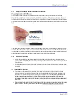
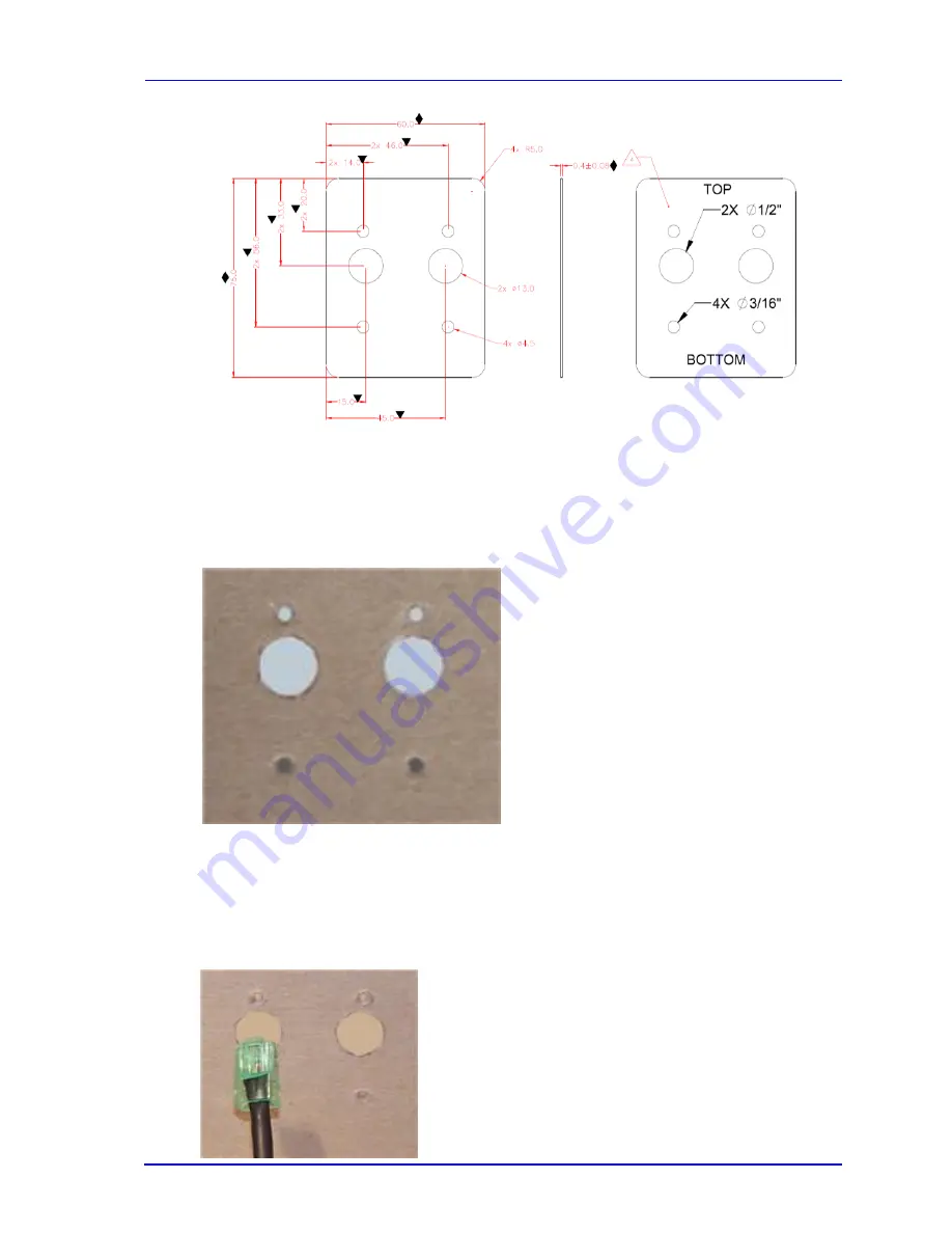
Using the Drill Template, locate and mark the two 14.0 mm (0.551 inches) access holes
(used for connecting the antenna power and the LED power and data cable to the
ViVOpay Kiosk III).
3.
Drill the four 4.4 mm (0.173) mounting holes using a number 17 drill bit.
4.
Drill the two 14.0 mm (0.551 inch) holes using a 35/64 drill bit.
5.
Remove the nuts from the four mounting screws.
6.
Route the end of the cable (80136204-001) with the RJ45 connector through the left 14.0
mm (0.551 inch) hole in to the kiosk. Make sure that the front of the antenna will be
properly oriented (not upside down) on the kiosk before inserting the four screws into the
mounting holes.


