background image

p.28

Identification Mode

If a user fails to be authorized, the FGR006 transmits the error signal to the controller.

For information on the system indication in the Reader Mode, refer to 11.Operatin

g Status of the FGR006 of this manual.

3.2

Authorization

RF + FINGER MODE:

1.

Present a registered card to the FGR006.

2.

When the card is recognized and the red light is turned on from the scanner, place a re

gistered fingerprint on the scanner.

3.

If the fingerprint is successfully authorized, the green LED is turned on and beep sound

is generated for one second. And the FGR006 transmits the ID information to the contr

oller according to the set output mode.

4.

If the fingerprint is not successfully authorized, beep sound is generated twice shortly.

And the FGR006 transmits fingerprint error signal (low active pulse) for 500ms if the ou

tput mode is set to 26/34Bit Wiegand.

RF-ONLY MODE:

1. Present a card which is registered without fingerprint.

2.

You don’t need to place your fingerprint on the fingerprint scanner.

3.

If the presented card is successfully authorized the green LED is turned on and beep sou

nd is generated for one second. And the FGR006 transmits the ID information to the co

ntroller according to the set output mode.

4.

If the fingerprint is not successfully authorized, beep sound is generated twice shortly.

And the FGR006 transmits fingerprint error signal (low active pulse) for 500ms if the ou

tput mode is set to 26/34Bit Wiegand.

4

Identification Mode

Summary of Contents for FINGER006SR

Page 1: ......

Page 2: ...Signal Output Applicable when output setting is 26 34bit Wiegand Open collec tor Output 1 In normal mode the FGR006 transmits Card ID only when authorization is a success But if you set Extension mode by application software the FGR006 transmits Card ID also when authorization is fail ed In this case you can get information of users whose authorization is failed However because a Ca rd ID is trans...

Page 3: ...twork Configuration 4 Wiring 4 1 Power Connections 4 2 Input Connection 4 3 Output Connections 4 4 External Reader Connection 9 Communication 1 Board ID Setting for RS485 RS422 Communication 1 1 For 8 0 0 and higher version of FGR006 8 1 0 and higher version of IP FGR006 4 0 0 and higher version of FGR006SR 1 2 For lower version of 8 0 0 FGR006 lower version of 8 1 0 IP FGR006 lower version of 4 0...

Page 4: ...tware 13 Troubleshooting 1 IDs have been transmitted from software to the device but I cannot access 1 1 Please check if IDs have been transmitted to controller too 2 The device does not go to setting mode after reading MASTER ID 2 1 MASTER ID may have changed 3 The device dose not communicate with PC 3 1 Please check wiring In the case of RS232 communication In the case of RS485 communication 3 2...

Page 5: ...scanner 6 I want to access with fingerprint only without card 6 1 Please check if IDENTIFICATION mode is set to USE 7 A fingerprint is not recognized 7 1 Please check the status of the fingerprint 7 2 If the status of the fingerprint is OK register your fingerprint again 8 I want to register 2 fingerprints for 1 ID 8 1 Please check if Dual Fingerprint Mode is set to USE 14 FCC REGISTRATION INFORMA...

Page 6: ... intended to alert the user to the presence of importa nt operating and maintenance servicing instructions in the literature accompanying the ap pliance WARNING To reduce the risk of fire or electric shock do not expose this appliance to rain or moisture WARNING 1 Be sure to use only the standard adapter that is specified in the specification sheet Usin g any other adapter could cause fire electri...

Page 7: ...this product in any way SAMSUNG is not liable for problems caused by unauthorized modifications or attempted repair 10 When cleaning do not spray water directly onto parts of the product Doing so may ca use fire or electric shock CAUTION 1 Do not drop objects on the product or apply strong blows to it Keep away from a locat ion subject to excessive vibration or magnetic interference 2 Do not insta...

Page 8: ...fety If the provided plug does not fit into your outlet consult an electrician for repla cement of the obsolete outlet 10 Protect the power cord from being walked on or pinched particularly at plugs convenie nce receptacles and the point where they exit from the apparatus 11 Only use attachments accessories specified by the manufacturer 12 Use only with cart stand tripod bracket or table specified...

Page 9: ...R006 iPASS IP FGR006 IDTECK FGR006SR provides high level security by integrating functions of proximity reader and fingerprint identification and permitting access only when card ID and a fingerprint are matched It is easy to install on metal mullions or flat surfaces and its elegant design and credible fing erprint recognition technology give you full satisfaction ...

Page 10: ...ard Network Communication via RS232 RS422 RS485 Max 255ch Upload Fingerprint Templates to PC Download Fingerprint Templates from PC Optional RS232C Stereo Jack is required Output format 26bit Wiegand Default and ABA Track II Option 1ea of External Reader Port 26 34bit Wiegand ABA TRACK II and 4 8bit Burst Signal Reception High Protection from Scratch and ESD Electro Static Discharge High Quality O...

Page 11: ...GR006SR Built in 13 56MHz 4 Contactless Smart Card Reader Smart Card Only Fingerprint Only Smart Fingerprint NOTE Auto Touch Sensor is optional for some product depending on their versi on FGR006 v7 4 0 or above IP FGR006 v8 1 0 or above and FGR006SR v 3 3 0 or abo ve Auto Touch Sensor is included FGR006 below v7 4 0 IP FGR006 below v8 1 0 and FGR006SR below v 3 3 0 Aut o Touch Sensor is optional ...

Page 12: ... Fingerprint Users Fingerprint Template Size 800 Bytes for 2 Fingerprint Templates Read Rang e Passive Type FGR006 IDK50 IMC125 Up to 2 inches 5cm IDC80 IDC170 Up to 4 inches 10cm IP FGR006 IPK50 Up to 2 inches 5cm IPC80 IPC170 Up to 4 inc hes 10cm FGR006SR ISK50 IHC80 IMC135 Up to 2 inches 5cm ISC80 Up to 4 inches 10cm Reading Time Card 30ms Verification Identification Time Less than 1sec Less th...

Page 13: ...mperature Fingerprint Mo dule 20 to 60C 4 to 140F RF Reader 35 to 65C 31 to 149F Operating Humidity 10 to 90 relative humidity non condensing Color Material Pearl Dark Gray and Light Gray Polycarbonate Weight Dimension W x H x T 259 5g 0 57lbs 66mm x 129mm x 52mm 2 6 x 5 1 x 2 0 Certification FCC CE KC Finger Module Specification Resolution 500dpi Capture Image Size 356 X 292 pixels Extraction Ima...

Page 14: ...Identifying Supplied Parts 5 p 9 Please unpack and check the contents of the box ...

Page 15: ... below RF Only Mode In this mode you need only card authorization to obtain access If card authorization is successful the corresponding card number will be transmitted to the controller This mode is useful for the user whose fingerprint is not applicabl e RF FINGER Mode In this mode you need both card and fingerprint authorizatio n to obtain access If card and fingerprint authorization is success...

Page 16: ...nge to an input port of the controller 1 6 Error Signal Output Applicable when output setting is 26 34bit Wiegand O pen collector Output Transmit ERROR Signal when any type of authorization is failed Transmitting ERROR signal needs connecting OK Signal wire Orange with black stripe to an input port of the controlle r What FGR006 Transmits In case of success In case of failure Normal Mode In case o...

Page 17: ...ailure Extension Mode Please refer to p 24 for output mode 1 7 Dual Finger Mode Dual Finger Mode is a function that allows a user to register two fingers for one ID so that t he user can receive authorization with either of the two registered fingers It can be used wh en user s fingers have injured 2 Product Explanation 2 1 Panel Description ...

Page 18: ...K Signal Out Orange with Black stripe Tamper Switch Out Purple Wiegand Data 0 In Pink Wiegand Data 1 In Cyan LED Control In Blue with White stripe Buzzer Control In White with Red stripe RS422 TX Gray RS422 TX Yellow RS422 RX Brown RS422 RX Blue RS485 communication you should combine Gray TX wire and Brown RX wi re Yellow TX wire and Blue RX wire and then connect the two combined wire s to a conve...

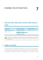
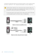
Page 19: ... 150m Belden 9514 22 AWG 8 conductor shielded Should use a wire that is thicker than a wire which can handle maximum current of the reader 2 Reader Connection Long distance between the product and ACU Access Control Unit may cause voltage drop For example if you install a reader that consumes 100mA current 100m away from ACU an d supply power to the reader from the ACU the voltage drop is 1V In th...

Page 20: ... reduce voltage drop Reduce the DC resistance of wire using a thick cable or add more wires to the wire in parallel If you connect 4 wires in parallel the DC resistance of the wire will be reduced to 1 4 of the DC resistance of the single wire Use separate power for the reader In case of using external power for the reade r and not supplying power from the ACU there is no voltage drop ...

Page 21: ...ally and drill one Ø1 2 hole in th e center of the two holes for the reader cable 2 Connect wires between the controller and the FGR006 and then put the reader cable i nto the center hole and install the main unit by using two 3 16 screws 3 Put the bezel into the main unit and until you hear the locking sound ...

Page 22: ...n on the power and then make all the DIP switches position up ON position 2 Initialization starts with buzzer sound When initializing process has finished the light o f fingerprint scanner is blinking 3 Place the DIP switch to the original position 2 2 For lower version of 8 0 0 FGR006 lower version of 8 1 0 IP FGR006 lowe r version of 4 0 0 FGR006SR Follow the steps below for initialization 1 Tur...

Page 23: ...vice is initialized all data stored in the device will be cleared and the defau lt setting values factory setting values will be reloaded Therefore the Initializatio n should be performed by authorized person only 3 FGR006 Network Configuration ...

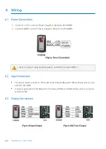
Page 24: ... Power Supply to Black wire of FGR006 Even in case of using external power you MUST connect GND 4 2 Input Connection The Green LED is turned on if the LED Control Input Blue with White stripe wire is conn ected to the GND A beep is generated if the Beeper Control Input White with Red stripe wire is connecte d to the GND 4 3 Output Connections ...

Page 25: ...p 20 Wiring 4 4 External Reader Connection ...

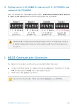
Page 26: ...ID can be set and Board ID 255 is used for system i nitialization thus you cannot use it as Board ID The method of setting Board ID differs depending on the version of product Therefore you should check the version and then set Board ID 1 1 For 8 0 0 and higher version of FGR006 8 1 0 and higher version of IP FGR 006 4 0 0 and higher version of FGR006SR Each of 8 DIP switches has assigned address ...

Page 27: ...Board ID on the same communication loop must not be duplicated If there a re duplicated Board ID in the same communication roof the communication error may occur 2 RS232 Communication Connection For RS232 communication you should use an external RS232C stereo jack Connect the RS232C stereo jack between the stereo jack plug on the bottom of the FG R006 and the COM1 or COM2 port of the Host Computer...

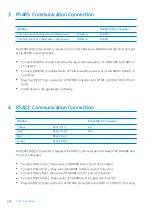
Page 28: ... Plug the RS232 9 pin connector of INC300 converter into COM1 or COM2 Port of Com puter Install and run the application software 4 RS422 Communication Connection FGR006 RS422 RS232 Converter Yellow RS422 Tx Rx Gray RS422 Tx Rx Blue RS422 Rx Brown RS422 Rx An RS422 RS232 converter is required for RS422 communication between the FGR006 and the Host Computer Connect RS422 Tx Yellow wire of FGR006 to ...

Page 29: ...p 24 RS422 Communication Connection Computer Install and run the application software ...

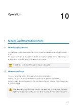
Page 30: ...of this manual NOTE For Master Card fingerprint data is not needed 1 2 Master Card Change You can change the Master Card again after system initialization Alternatively you can change the Master Card using the application software Using the application software keeps the user data unchanged Refer to the software manu al for more details If the device is initialized all data stored in the device wi...

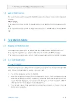
Page 31: ... from the FGR006 4 beeps If you present an unregistered user card it will be newly registered to the FGR006 3 beeps 2 2 User Card Registration RF FINGER MODE After presenting the user card you d like to register you should enter the desired fingerprint twice Follow the steps below to register a new user card 1 Present the designated card to the FGR006 2 When the red light is turned on from the fin...

Page 32: ...r don t place the fingerprint o n it and wait until the red light turns off automatically 3 After the registration is successfully completed you ll hear 3 beeps 4 If you d like to register more user cards repeat the procedure above Or if you d like to finish registration present the Master Card to return to the Reader Mode NOTE You can delete user cards by using the application software 3 Reader M...

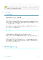
Page 33: ... the set output mode 4 If the fingerprint is not successfully authorized beep sound is generated twice shortly And the FGR006 transmits fingerprint error signal low active pulse for 500ms if the ou tput mode is set to 26 34Bit Wiegand RF ONLY MODE 1 Present a card which is registered without fingerprint 2 You don t need to place your fingerprint on the fingerprint scanner 3 If the presented card i...

Page 34: ... the fingerprint scanner Keep the fingerprint s till on the canner until the red light is turned off 3 If the fingerprint is successfully authorized the green LED is turned on and beep sound is generated for one second And the FGR006 transmits the ID information to the contr oller according to the set output mode 4 If the fingerprint is not successfully authorized the FGR006 will make 2 beeps and ...

Page 35: ...p 30 External RS232C Stereo Jack Option ...

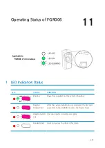
Page 36: ...ing Power has supplied and the system is booting Register Master Card After the system initialization is completed the first card presented to the FGR006 becomes the Master Card Registration M ode You can register or delete user cards Reader Mode Users can access the door in this mode ...

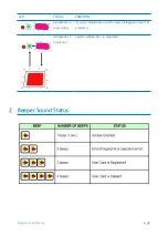
Page 37: ...und Status Initialization is proceeding If system initialization is performed all registered users ar e deleted Initialization C ompletion System initialization is completed LED STATUS FUNCTION 2 Beeper Sound Status ...

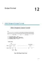
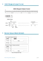
Page 38: ...Output Format 12 p 33 1 26bit Wiegand Output Format ...

Page 39: ...p 34 Normal Output Mode Default 2 34bit Wiegand Output Format 3 Normal Output Mode Default ...

Page 40: ...Output Format p 35 4 Extension Output Mode Selectable using the softwar e ...

Page 41: ...ng when registering a fingerprint 6 6 I want to access with fingerprint only without card 7 7 A fingerprint is not recognized 8 8 I want to register 2 fingerprints for 1 ID 1 IDs have been transmitted from software to the devic e but I cannot access 1 1 Please check if IDs have been transmitted to controller too If IDs have been transmitted to the device only and have not been transmitted to contr...

Page 42: ...f the manual and initialize the devi ce I The first card the device reads after the initialization becomes a master card See Operation MASTER CARD registration mode for more information If the problem persists please contact service center 3 The device dose not communicate with PC 3 1 Please check wiring See Communication of the manual and check if the wiring is good In the case of RS232 communica...

Page 43: ...t in the device is same with communication ID set in a soft ware See Communication Board ID Setting for RS485 RS422 Communication and chec k a communication address set in the device 2 When you use several devices together communication addresses set in the devices sh ould be different from each other 3 Check if baud rate is same with baud rate set in a software If you initialize the device baud r...

Page 44: ...persists please contact service center 5 Errors keep occuring when registering a fingerprint 5 1 Check if the status of the fingerprint is good If something had been attached to fingerprint or fingerprint had had a scar when you regist ered fingerprint recognition may not work properly Remove it 5 2 Place your fingerprint on the right position of the fingerprint scanner If not fingerprint recognit...

Page 45: ...print If something is attached to fingerprint fingerprint recognition may not work properly Remove it If a fingerprint has a scar fingerprint recognition may not work properly Register other fingerprint without a scar 7 2 If the status of the fingerprint is OK register your fingerprint again If something had been attached to fingerprint or fingerprint had had a scar when you regist ered fingerprin...

Page 46: ...erprint Mode is set to USE If you use Dual Fingerprint Mode you can register 2 fingerprints for 1 ID just in case a finger print is injured Set DUAL FINGER MODE to USE and transmit it to the device If the problem persists please contact service center ...

Page 47: ...e received including interference that may caus e undesired operation This equipment has been tested and found to comply with the limits for a Class A Digital De vice pursuant to Part 15 of the FCC rules These limits are designed to this equipment gener ates uses and can radiate radio frequency energy and if not installed and used in accordan ce with the instructions may cause harmful interference...

Page 48: ...g Gangseo Gu Seoul 157 030 Korea Tel 82 2 2659 0055 Fax 82 2 2659 0086 E mail webmaster idteck com Website www idteck com E Training Center http www idtecktraining com IDTECK Production Facility and RMA Center 2F 89 4Dodang Dong Weonmi Gu Bucheon Si Gyeonggi Do 420 130 Korea Tel 82 2 2659 0055 Fax 82 2 2659 0086 E mail webmaster idteck com Website www idteck com E Training Center http www idtecktr...

Reviews: