23
8.4.4 READER CONNECTIONS (EXTERNAL READER)
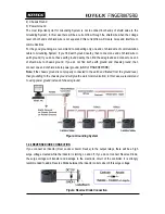
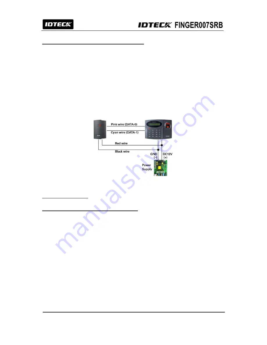
Proximity Reader Connection
- Connect (+) wire of
FINGER007SRB
to +12V (Red wire).
- Connect (-) wire of
FINGER007SRB
to GND (Black wire).
- Connect DATA0 wire of
FINGER007SRB
to DATA0 (Pink wire).
- Connect DATA1 wire of
FINGER007SRB
to DATA1 (Cyan wire).
CAUTION:
If the controller and the e
xternal reader
use separate power sources, you must connect
the GND between the controller and the e
xternal reader
.
Compatible Readers(External Reader)
FINGER007SRB/006SRB VA.0.0 or higher. (WIEGAND output function can
be used).
Figure: Reader Connection
9. COMMUNICATION
9.1 RS232 COMMUNICATION PORT CONNECTION
A 9-PIN connector (Serial Communication Connector, Female) is required to connect the
FINGER007SRB
to the PC via RS232 communication.
Please follow the instructions.
- Connect RS232-TX (Black wire with White stripe) port of
FINGER007SRB
to the PIN 2 of the 9-PIN
connector.
- Connect RS232-RX (Red wire with White stripe) port of
FINGER007SRB
to the PIN 3 of the 9-PIN
connector.
- Connect RS232-GND of
FINGER007SRB
to the PIN 5 of the 9-PIN connector.
- Plug in the 9-PIN connector to COM1 or COM2 port of the PC.
- Install and run
FINGER007SRB
Application Software.
CAUTION:
The firmware upgrade may not succeed if the distance between the PC and the device is
too far. The USB-to-serial converter is recommended if the PC has no COM ports.
Summary of Contents for Finger007SRB
Page 1: ...User s Manual Fingerprint Stored Smart Card Access Controller Rev A 1 0 ...
Page 31: ...31 12 1 SETUP MENU F1 ...
Page 36: ...36 12 2 SETUP MENU F2 ...
Page 37: ...37 ...
Page 46: ...46 12 3 SETUP MENU F3 ...
Page 59: ...59 17 TEMPLATE ...

