background image


33 


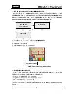
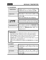
12.1.4. READER #1 MODE 


12.1.5. READER #2 MODE 


4. READER 1 MODE 
RF ONLY 

4. READER 1 MODE 
->RF + PW   

Access Modes for Reader #1 
1. RF ONLY:

 Users can access the door by presenting their card or entering their ID number. 

2. RF + Password:

 Users can access the door by presenting their card or entering their ID 

number and then verifying their identity by a Password. 

You can decide which combination of RF card, password 
verification you wish to use on Reader #1.   
To change the Access Mode for Reader #1, press 

<ENT>

, select 

the “

DESIRED MODE

” by pressing 

<4>

 or 

<6>

, and then press 

<ENT>

 again to confirm.


5. READER 2 MODE 
RF ONLY 

5. READER 2 MODE 
->RF + PW   

Access Modes for Reader #2 
1. RF ONLY:

 Select this option if Reader #2 is operating without password verification. 

2. RF+ Password:

 Select this option if Reader #2 uses password verification. 

If you have an external reader connected to the 
FINGER007SRB (referred to herein as Reader #), you must 
adjust this setting according to what access mode is used on 
Reader #2. 
To change the Access Mode for Reader #2, press 

<ENT>,


select the desired mode by pressing 

<4> 

or 

<6>

, and then 

press 

<ENT>

 again to confirm.


  If communication has problem;   

1.


Check the status of COMM Address Registration (It has 
to be same as Application Software.) 

2.


Check the matching Communication Speed (Baud rate) 
(It has to be same as Application Software.) 

3.


Check the matching port between PC communication 
port and Application Software port. 

4.


Check the setting for communication environment of 
Application Software.   

Parity Bit: NONE   
Data Bit: 8bit   

Stop Bit: 1bit   

Summary of Contents for Finger007SRB

Page 1: ...User s Manual Fingerprint Stored Smart Card Access Controller Rev A 1 0 ...

Page 2: ...7 1 2 RECOMMENDED CABLE TYPE 16 7 2 CHECK POINT DURING INSTALLATION 16 7 2 1 TERMINATION RESISTOR 16 7 2 2 HOW TO CONNECT TERMINATION RESISTORS 17 7 2 3 GROUNDING SYSTEM FOR COMMUNICATION CABLE 17 7 2 4 REVERSE DIODE CONNECTION 18 8 INSTALLATION OF THE PRODUCT 19 8 1 TEMPLATE 19 8 2 SYSTEM INITIALIZATION USING INITIALIZATION BUTTON 20 8 3 WALL MOUNT INSTALLATION 20 8 4 WIRING 21 8 4 1 POWER 21 8 4...

Page 3: ...2 SETTING CHANGES 30 12 1 SETUP MENU F1 31 12 1 1 TIME SETTING 32 12 1 2 COMMUNICATION ADDRESS 32 12 1 3 BAUD RATE 32 12 1 4 READER 1 MODE 33 12 1 5 READER 2 MODE 33 12 1 6 MASTER ID REGISTRATION 34 12 1 7 SYSTEM INITIALIZATION 34 12 1 8 CARD ID CLEAR 35 12 1 9 EVENT CLEAR 35 12 1 10 TIME SCHEDULE CLEAR 35 12 2 SETUP MENU F2 36 12 2 1 TIME SCHEDULE 38 12 2 2 HOLIDAY TIME SCHEDULE 39 12 2 3 HOLIDAY...

Page 4: ... 4 1 FIRMWARE VERSION 51 12 4 2 MEMORY TEST 51 12 4 3 OUTPUT TEST 51 12 4 4 LCD TEST 52 12 4 5 KEYPAD TEST 52 12 4 6 READER TEST 53 12 4 7 INPUT DIP SWITCH TEST 53 12 4 8 COMMUNICATION TEST 54 13 APPENDIX 54 13 1 DEFAULT VALUES FOR PARAMETERS 54 13 2 DEFAULT OUTPUT SETTINGS FOR INPUT OUTPUT RELATIONS 55 14 FCC REGISTRATION INFORMATION 56 15 WARRANTY POLICY AND LIMITATION OF LIABILITY 57 16 HOW TO ...

Page 5: ...short circuit parts possibly resulting in fire or electric shock Never spill liquid of any kind on the product 7 Never disassemble this product by yourself take the unit to a qualified service center whenever service or repair is required Opening or removing the covers may expose you to dangerous voltages or other risks Also incorrect reassembly can cause electric shock when the unit is subsequent...

Page 6: ...PRG2000B to encode fingerprint information onto the card The IDTECK FINGER007SRB is capable of controlling one External Reader for Anti Pass Back application Four independent input ports can be utilized for a wide variety of applications including Exit Buttons Door Contacts PIR Sensors and Fire Detection equipment Actions to be taken and time settings can be programmed with the front keypad or via...

Page 7: ... Model FINGER007SRB CPU 32Bit Microprocessor and Dual 8Bit Microprocessor Memory Fingerprint Module Program Memory 1M Byte Flash Memory Controller Program Memory 128K Byte Flash Memory Data Memory 1M Byte Flash Memory Users Fingerprint Users 10 000 50 000 Users Event Buffer 10 000 50 000 Event Buffer The sum of users and events cannot exceed 60 000 Read Range Passive Type ISC80 Up to 4 Inches 10 c...

Page 8: ... 32 to 122 F Controller 15 to 70 C 5 to 158 F RF Reader 35 to 65 C 31 to 149 F Operating Humidity 10 to 90 Relative Humidity Non condensing Color Material Dark Pearl Gray Polycarbonate Dimension W x H x T 6 36 x 5 28 x 1 9 161 5mm x 134mm x 48 5mm Weight 525 g 1 21lbs Certification FCC Class A part 15 UL294 MIC Fingerprint Module Specifications Capture Time 0 2 Normal 0 7 Secure Sec Verification T...

Page 9: ...xample from and activated sensor or if the Exit Button pressed the controller generates and logs an appropriate response All events are kept in its memory and sent to the PC The access controller is a true standalone device that in the event of a malfunction will not affect other units even if used in conjunction with one another Operation with PC All event transactions can be managed via the PC T...

Page 10: ...nerated from dual TTL output Time Schedule You can program 10 Time Schedules and apply one Time Schedule to each user Each Time Schedule has 8 different time zones from Monday to Sunday 7 Time Zones and one holiday Each time zone has 5 different time codes so you can program 5 different time codes to each day Also you can program Time Schedule for individual inputs and outputs Note that the Time S...

Page 11: ...Open Alarm The FINGER007SRB can report the open status of the door if the door is not closed within a certain length of time default 3 sec after the door is opened following a normal access procedure If this is the case an alarm signal can be sent to the output port and the alarm event will be saved in the event buffer so that it can be uploaded to the PC when communication is established If the d...

Page 12: ...rns on with Relay 1 operation The yellow LED turns on with Relay 2 operation Finger Print Scanner It is used to verify the fingerprint encoded in the card by PRG2000KIT 16 Numeric Keypad Card data registration delete and various functions on and off are possible through keypad input without host computer control Function Keypad There are four function keys F1 F2 F3 and F4 LCD Display 16 Numeric Ke...

Page 13: ...reen LEDs are twinkling during Serial and TCP IP communication If the LAN is connected normally during TCP IP communication green LED is turned on but in the collision status 2 red LED is turned on Figure The Communication Display LED in the Rear View Temper Button Initialization Button 1 2 3 4 ...

Page 14: ...Sensor DOOR CONTACT Yellow with Red Stripe Aux Input 1 IN1 OK Input Reader Mode Green Aux Input 2 IN2 Error Input Reader Mode Green with White Stripe EXTERNAL READER PORT CON5 Wiegand Data 0 DATA0 Pink Wiegand Data 1 DATA1 Cyan OUTPUT CON5 TTL Output 1 TTL1 DATA0 Orange with White TTL Output 2 TTL2 DATA1 Brown with White Stripe OK Signal Out OK Out Not Use Green with Red Stripe Error Signal Out Er...

Page 15: ...mmunication to the PC 7 INSTALLATION TIPS CHECK POINT Installing the FINGER007SRB is an easy task It can be installed with common hand tools and readily available communications wires This section provides information about wiring wire runs and other information to make the installation quick and easy 7 1 CHECK POINTS BEFORE INSTALLATION 7 1 1 SELECTION OF CABLE System installation cabling will be...

Page 16: ...shielded RS232 Cable Converter Host PC Belden 9829 24 AWG 2 twisted pair shielded RS485 Cable FINGER007SRB FINGER007SRB FINGER007SRB Converter Belden 9829 24 AWG 2 twisted pair shielded RS422 Cable FINGER007SRB FINGER007SRB FINGER007SRB Converter Belden 9830 24 AWG 3wisted pair shielded Thicker wires are needed if you connect a reader with high current consumption 7 2 CHECK POINT DURING INSTALLATI...

Page 17: ...al is overlapped by the reflected signal In this case it is recommended to add Termination Resistors to the end of the receiver lines A 120Ω resistor can be used for Termination Resistor in parallel between the receiver lines A and B for 2 wires RS485 system or RX and RX for 4 wires RS422 system A Termination Resistor of less than 90Ω should not be used and no more than 2 terminations should be us...

Page 18: ... you do not find both earth ground and chassis ground then connect one end of shield wire to power ground GND of FINGER007SRB Note if the chassis ground is not properly connected to the earth and floated from the ground level then grounding to the chassis ground will give the worst communication in this case we recommend to using power ground instead of chassis ground Figure Grounding System 7 2 4...

Page 19: ...own below If the gang box is installed on the wall skip this step Using 2 screws install wall mount to the wall Caution Before mounting the FINGER007SRB unit to the Wall Mount bracket an operational test of the unit should be completed because the locking pins will lock the unit to the Wall Mount Removing the unit from the Wall Mount bracket after it has been snapped in place may cause damage to t...

Page 20: ... FINGER007SRB 2 Initialization is progressing 3 Rebooted automatically after Initialization Figure The Position of Initialization Button 8 3 WALL MOUNT INSTALLATION 1 Position the wall mount template to the location at which you want to install the unit and mark 4 drilling positions Drill 6 32 holes for at least 4 mounting points 2 Drill a 1 2 hole on the center of the wall mount 3 Using 4 screws ...

Page 21: ...re Auxiliary Input Connection Applied IN1 IN2 Connect one wire from an Auxiliary Input device to one of the IN1 Green wire IN2 Green with White stripe Connect the other wire from the Auxiliary Input device to GND Black wire Figure Input Devices Connection 2 2K Resistance Connection for Cut Off Check You have to connect a 2 2K Resistor between the input wire e g Orange wire and the GND to apply the...

Page 22: ...onnect GND Black wire port to wire of Door Lock Devices Alarm Device Connection Relay 2 Connect COM port of Relay 2 White to 12V Red wire Connect NO port of Relay 2 Purple to wire of Alarm Devices Connect GND Black wire port to wire of Alarm Devices Figure Door Lock Alarm Device Connection CAUTION Please add one diode as shown above A fast recovery diode Current Min 1A 1N4001 1N4007 or similar is ...

Page 23: ...ICATION 9 1 RS232 COMMUNICATION PORT CONNECTION A 9 PIN connector Serial Communication Connector Female is required to connect the FINGER007SRB to the PC via RS232 communication Please follow the instructions Connect RS232 TX Black wire with White stripe port of FINGER007SRB to the PIN 2 of the 9 PIN connector Connect RS232 RX Red wire with White stripe port of FINGER007SRB to the PIN 3 of the 9 P...

Page 24: ...rter Connect RS422 RX Brown wire of FINGER007SRB to RS422 TX port of converter Connect RS422 RX Blue wire of FINGER007SRB to RS422 TX port of converter Plug in the RS232 9PIN connector of the converter to the COM1 or COM2 port of the PC Install and run FINGER007SRB Application Software Figure RS422 Communication between FINGER007SRB and the PC 9 2 2 RS 422 CONNECTION MULTIPLE FINGER007SRB CONNECTI...

Page 25: ... the converter Connect RS422 RX of the one FINGER007SRB to TX port of the converter Plug in the RS232 9PIN connector of the converter to the COM1 or COM2 port of the PC Install and run FINGER007SRB Application Software Figure RS422 Communication between FINGER007SRBs and PC 9 3 TCP IP COMMUNICATION PORT CONNECTION OPTIONAL Optional TCP IP module is required to use TCP IP communication between the ...

Page 26: ...re TCP IP Converter between FINGER007SRB Device and Host PC INTERFACE FINGER007SRB ILAN422 LINE COLOR RS232 TX CON2 RX RS232 DSUB9 BLACK WHITE RX CON2 TX RS232 DSUB9 RED WHITE GND CON2 GND BLACK RS422 TX CON3 RX RS422 CONNECTOR GRAY TX CON3 RX RS422 CONNECTOR YELLOW RX CON3 TX RS422 CONNECTOR BROWN RX CON3 TX RS422 CONNECTOR BLUE ...

Page 27: ...e Master ID default 00000000 and press the ENT key There are 4 main Setup menus and you automatically get into SETUP MENU F1 first You can move to other Setup menus by pressing the F1 key for SETUP MENU F1 F2 key for SETUP MENU F2 F3 key for SETUP MENU F3 and F4 key for SETUP MENU F4 There are setting items in the main Setup Menu and you can scroll up or down the menu by pressing the 4 or 6 key If...

Page 28: ...t data from the memory Because entering the Setup Mode itself generates an event you must always initialize the event memory prior to changing the maximum ID number setting If you attempt to change the setting with some event data still in the memory the LCD will display EVENT MEMORY NOT EMPTY Figure 2 error message NOTE If you attempt to reduce the ID memory size to a value lower than the current...

Page 29: ... on Alarms Unregistered Card Password Time Schedule Door Error When an unregistered card is read wrong password is input over the Time Schedule and access wrong door the access is denied and the alarm Relay 2 is activated for 3 seconds Defaults with RED LED on 11 2 DEFAULT SETTING When you operate the FINGER007SRB first time or you initialize the FINGER007SRB the controller will set up all values ...

Page 30: ...matically get into SETUP MENU F1 first You can move to other setup menus by pressing the F1 key for SETUP MENU F1 F2 key for SETUP MENU F2 F3 key for SETUP MENU F3 and F4 key for SETUP MENU F4 There are setting items in the main setup menu and you can scroll up or down the menu by pressing the 4 or 6 key If you press the ESC key then the FINGER007SRB will exit the Setup Mode and return to normal o...

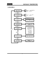
Page 31: ...31 12 1 SETUP MENU F1 ...

Page 32: ...t on the application software It is also important to make sure each device on a loop has a unique address To change the communication address of the FINGER007SRB press ENT enter the desired 2 Digit address in the 00 31 range and then press ENT again to confirm 2 COMM ADDRESS 00 Baud Rate is the measurement of the serial communication speed As with the communication address the baud rate you set h...

Page 33: ...ect this option if Reader 2 is operating without password verification 2 RF Password Select this option if Reader 2 uses password verification If you have an external reader connected to the FINGER007SRB referred to herein as Reader you must adjust this setting according to what access mode is used on Reader 2 To change the Access Mode for Reader 2 press ENT select the desired mode by pressing 4 o...

Page 34: ...d communication speed is maintained even though initialization is processed 7 SYSTEM INIT 7 SYSTEM INIT 1 YES 0 NO WAITING 6 MASTER ID Master ID is the number card that you use to enter the Setup Mode For security reasons it is advisable that you change the default Master ID immediately and keep the new Master ID card confidential CAUTION Beware that if you forget the Master ID you cannot access t...

Page 35: ...make sure to check whether or not the data stored in the device is not needed since it will be deleted after the event clear To clear the event data stored in the memory press ENT and then press 1 to confirm If you wish to cancel and exit press 0 instead 9 EVENT CLEAR 9 EVENT CLEAR 1 YES 0 NO T S Clear allows you to delete all the data related to time scheduling such as Time Schedules Holiday and ...

Page 36: ...36 12 2 SETUP MENU F2 ...

Page 37: ...37 ...

Page 38: ... S information such as T S code day and time interval and time period Press 2 or 8 to scroll up or down the time schedule code 01 10 and the day of the week Mon Sun and holiday Press 4 or 6 to scroll up or down the time interval The holiday in this time schedule will be linked to the holiday schedule code Select a time schedule code day and Interval and press ENT Enter the start and closing time f...

Page 39: ...de 01 10 Press 4 or 6 to scroll up or down the time interval Select a Holiday T S code and index and press ENT Enter the date in the MM DD format then press ENT to save the new holiday definition Once all information is entered press ESC to return to the menu NOTE You can also define time schedule codes using the Application Software For more information please refer to the Software Manual The Hol...

Page 40: ... wish to allow RF Only Access from 08 00 to 18 00 while using RF PW verification for the rest of the time you can proceed as follows 1 Set READER 1 MODE to RF PW Mode 2 Define T S code 01 so that it can include Time Interval between 08 00 and 18 00 for the desired days of the week 3 Here in Reader T S press ENT enter the 2Digit T S code In this case 01 and then press ENT again to confirm 4 To retu...

Page 41: ...00 When you press INPUT 1 EXIT BUTTON Relay 1 is activated for 3 seconds z 15 16 00 10 Time Schedule Code eg 15 OUTPUT T S 01 01 00 00 00 During set TIME SCHEDULE time Relay 2 is operating TIME SCHEDULE should be set prior to 15 16 setting z 19 21 00 01 Enable or Disable Press 4 or 6 to select 01 Enable or 00 Disable then ENT to confirm the change NOTE The 14 Duress Modem Setting allows you to dec...

Page 42: ...it of 1 10 second or 100ms for the In Output definition To change the setting press ENT and press 4 or 6 to select the desired time unit and press ENT to confirm 7 APB SETUP DISABLE 7 APB SETUP ENABLE Anti Pass Back Setting Menu Items z DISABLE The Anti Pass Back feature is disabled z ENABLE The Anti Pass Back feature is enabled z ALL CLEAR All Anti Pass Back flags are reset and access will be all...

Page 43: ...nput you cannot gain access via the keypad without a card To enable or disable PIN Input press ENT and press 4 or 6 to select ENABLE or DISABLE and then press ENT again to confirm 9 EVENT ALARM ENABLE 9 EVENT ALARM DISABLE Event Alarm allows you to decide whether to enable or disable the event memory full alarm If you enable Event Alarm the FINGER007SRB beeps with an alarm message when the event m...

Page 44: ...egular access process Following a successful access process access will be granted as usual but at the same time a duress alarm will be generated NOTE To learn about how to change the duress alarm output settings please refer to 12 2 5 In Output Definition 11 DOOR ALARM 03 11 DOOR ALARM 99 Door Open Alarm Time refers to the delay between the time at which the Door Relay time finishes and the time ...

Page 45: ...ISABLE The buzzer generates a beep when a button on the keypad is pressed when a card is read when an error occurs etc To enable or disable the buzzer sound press ENT and press 4 or 6 to select ENABLE or DISABLE and press ENT to confirm NOTE The buzzer beeps regardless of this setting when you exit the Setup Mode when a memory alarm is activated or whenBuzzerOutputisdefinedin In OutputDefine 14 TT...

Page 46: ...46 12 3 SETUP MENU F3 ...

Page 47: ...ation z TS Time Schedule If you wish to apply a certain time schedule to the cardholder enter the T S code If you wish to allow the cardholder round the clock access enter 0 RD Reader Code To use both Reader 1 and 2 for the cardholder Enter 0 To use just Reader1 enter 1 To use just Reader2 enter 2 NOTE The TS and RD fields do not appear if the FINGER007SRB is set in Reader Mode 1 ID DELETE ENTER I...

Page 48: ... The LCD will show the information of the card you have selected in the previous step or the first card on the list Press 4 or 6 to view the information of the previous or next card The FIRST ID or LAST ID message will appear if you are viewing the first or last ID If there is no card data the LCD will display the MEMORY EMPTY message If your FINGER007SRB is set in Reader Mode the TS and RD values...

Page 49: ...ory space between IDs and event transactions The total number of IDs and event transactions combined is a maximum of 60 000 The default setting is 10 000 users and 50 000 event transactions If you increase the maximum number of IDs the maximum number of events decreases in the same proportion and vice versa To change the memory partition setting press ENT and press 4 or 6 to select 10000 50000 200...

Page 50: ...2345 The number of event transactions is displayed This count automatically increases or decreases as new events occur or the existing events are uploaded to the PC The LCD on the left shows that the total of 12345 event transactions is stored in the memory ...

Page 51: ...ate date 2 MEMORY TEST Memory Test allows you to test the memory of the FINGER007SRB To begin the test press ENT If the test is successful the LCD will display the TEST PASSED message Press any key to finish the test If the test is unsuccessful the LCD will display the TEST FAILED message Press any key to finish the test and try again If the problem persists please contact your local IDTECK dealer...

Page 52: ...ey to exit OUTPUT 1 OFF PRESS ANY KEY 4 LCD TEST LCD Test allows you to test the LCD of the FINGER007SRB To begin the test press ENT Once the test begins the LCD will display a series of different screens Ensure that all the screens on the LCD are properly displayed The test ends with the display of the firmware update date YYYY MM DD After the test is finished press any key to exit AAAAAAAAAAAAAA...

Page 53: ...NING READER 1 12345678 7 INPUT TEST Input Test allows you to check the status of Input Ports and DIP switches Communication Address Setting Switches To begin the test press ESC 1 DIP Switch 1 ON 2 OFF It shows how the DIP switch on the back of the FINGER007SRB is set 2 Input 1 4 0 OFF Disabled Input 1 4 1 ON Enabled Input 1 4 2 Input Disconnected 3 Input 5 The status of the tamper switch in the FI...

Page 54: ...ll Date 00 00 13 Holiday Code 00 All holiday codes 14 Time Schedule Assigned to Reader 1 Mode 00 15 Time Schedule Assigned to Reader 2 Mode 00 8 COMM TEST COMM Test allows you to test communication Prior to the test connect the RS232 RX wire Black wire with White stripe and the RS232 TX wire Red wire with Black stripe together To begin the test press ENT If the test is successful the LCD will disp...

Page 55: ... 00 03 00 00 00 14 DURESS MODE 03 00 00 00 00 15 OUTPUT TIME SCHEDULE 00 00 00 00 00 16 INPUT TIME SCHEDULE Input 1 Input 2 Input 3 Input 4 Input 5 00 00 00 00 00 17 DR OPEN ALARM Relay 1 Relay 2 TTL 1 TTL 2 BUZZER 00 03 00 00 00 18 CUT OFF ALARM Input 1 Input 2 Input 3 Input 4 Input 5 00 00 00 00 00 19 INPUT EVENT Input 1 Input 2 Input 3 Input 4 Input 5 01 01 01 01 01 20 EMERGENCY IN Input 1 Inpu...

Page 56: ...ipment has been tested and found to comply with the limits for a Class A Digital Device pursuant to Part 15 of the FCC rules These limits are designed to this equipment generates uses and can radiate radio frequency energy and if not installed and used in accordance with the instructions may cause harmful interference to radio communications However there is no guarantee that interference will not...

Page 57: ...CULAR PURPOSE IDTECK does not and cannot know who is present what property is located where this product will be used it would be extremely difficult to determine the actual damages that may result from a failure of the product to perform as anticipated and the low price of this product is based upon the nature of the product provided and the limited liability that IDTECK assumes IDTECK IS NOT RES...

Page 58: ...roduct along with the RAM Code and send it to IDTECK RMA Center Product without RMA Code is not accepted If you have any questions or problems regarding the RMA services please contact us using the following contact information below Friendly representatives at IDTECK are always standing by to provide the best after sales services IDTECK Headquarter 5F Ace Techno Tower B D 684 1 Deungchon Dong Gan...

Page 59: ...59 17 TEMPLATE ...

Page 60: ...K Co Ltd The specifications contained in this manual are subject to change without notice at any time 5F Ace Techno Tower B D 684 1 Deungchon Dong Gangseo Gu Seoul 157 030 Korea Tel 82 2 2659 0055 Fax 82 2 2659 0086 E mail webmaster idteck com ...

Reviews: