background image

Installation Tips & Check point

p.23

st class earth grounding; however it is not so easy to bring the earth ground to the communi

cation cable and also the installation cost is raised.

There will be three grounding point where you can find during installation;

1.

Earth Ground

2. Chassis Round

3.

Power Ground

The most important point for Grounding System is not to connect both ends of shield wires

to the Grounding System; in this case there will be a current flow through the shield wire w

hen the voltage level of both ends of shield wire is not equal and this current flow will creat

e noise and interfere to communications.

For the good grounding, we recommend to connecting only one end of shield wire of com

munication cable to Grounding System; If you find earth ground nearby, then connect one e

nd of shield wire to earth ground; If you do not have earth ground nearby, then find chassis

ground and connect one end of shield wire to chassis ground; If you do not find both earth

ground and chassis ground, then connect one end of shield wire to power ground. (GND of

FINGER007)

If the chassis ground is not properly connected to the earth and floated from the g

round level, then grounding to the chassis ground will give the worst communicati

on; in this case we recommend using power ground instead of chassis ground.

Summary of Contents for IP-FINGER007

Page 1: ......

Page 2: ... Functions 1 1 Standalone Operation 2 Product Description 2 1 Front View 2 2 Rear View 2 3 Color Coded Wiring Table 3 Option 8 Installation Tips Check point 1 Check Points before Installation 1 1 Installation Layout 1 2 Recommended Cable Type 2 Check Point during Installation 2 1 Termination Resistor ii 1 3 4 6 7 10 11 12 12 12 15 16 17 18 19 20 20 20 21 21 21 ...

Page 3: ...ock Power Fail Safe Connection Relay 1 Door Lock Power Fail Secure Connection Relay 1 Alarm Device Connection Relay 2 Wiegand Data Connection Applicable to Reader Mode 3 4 Reader Connections External Reader Proximity Reader Connection Compatible Readers External Reader FINGER007 IP FINGER007 FINGER007SR 10 Communication 1 RS232 Communication Port Connection 2 RS 422 Communication Port Connection 2...

Page 4: ... 1 Time Setting 1 2 Communication Address 1 3 BAUD RATE 1 4 Reader1 Mode 1 5 Reader 2 Mode 1 6 Master ID Registration 1 7 System Initialization 1 8 Card ID Clear 1 9 Event Clear 1 10 Time Schedule Clear 2 Setup Menu F2 2 1 Time Schedule 2 2 Holiday T S 2 3 Holiday Code 2 4 Reader Time Schedule 2 5 Input Output Definition 2 6 Output Time Setting 2 7 Anti Passback 2 8 RF PIN Input 2 9 Event Alarm 2 ...

Page 5: ...pad Test 4 6 Reader Test 4 7 Input DIP Switch Test 4 8 Communication Test 4 9 Identification Mode 4 10 Dual Fingerprint Mode 4 11 ADAPTIVE MODE 4 12 FP STATUS 4 13 HIGH SECURITY 설정 4 14 FP QUALITY 4 15 FP LEVEL 4 16 Fingerprint Module Version 4 17 Fingerprint Count 4 18 Fingerprint Module Test 4 19 Fingerprint Device Information Check 14 APPENDIX 1 Default Values for Parameters 2 Default Output Se...

Page 6: ...d but does not work when inputting card number 5 1 Please check if Keypad is set to USE 6 A buzzer keeps making sounds Bee Bee Bee 6 1 Please check if the door is closed well 7 A buzzer keeps making sounds Bee 7 1 Check if the tamper switch is pressed well 8 SCHEDULE ERROR appears on the LCD when a card is read 8 1 Please check Time Schedule set for the ID 9 ACCESS DOOR ERR appears on the LCD when...

Page 7: ...p vii 16 Template 17 FCC REGISTRATION INFORMATION 18 RMA Request 95 95 96 ...

Page 8: ...he user to the presence of importa nt operating and maintenance servicing instructions in the literature accompanying the ap pliance WARNING To reduce the risk of fire or electric shock do not expose this appliance to rain or moisture WARNING 1 Be sure to use only the standard adapter that is specified in the specification sheet Usin g any other adapter could cause fire electrical shock or damage ...

Page 9: ...way SAMSUNG is not liable for problems caused by unauthorized modifications or attempted repair 10 When cleaning do not spray water directly onto parts of the product Doing so may ca use fire or electric shock CAUTION 1 Do not drop objects on the product or apply strong blows to it Keep away from a locat ion subject to excessive vibration or magnetic interference 2 Do not install in a location sub...

Page 10: ...fety If the provided plug does not fit into your outlet consult an electrician for repla cement of the obsolete outlet 10 Protect the power cord from being walked on or pinched particularly at plugs convenie nce receptacles and the point where they exit from the apparatus 11 Only use attachments accessories specified by the manufacturer 12 Use only with cart stand tripod bracket or table specified...

Page 11: ... th e desired level of security and convenience for individual users or different groups of users The Star FINGER007 iPASS IP FINGER007 IDTECK FINGER007SR is capable of controlling one External Reader for Anti Pass Back application Four independent input ports can be util ized for a wide variety of applications including Exit Buttons Door Contacts PIR Sensors and Fire Detection equipment Actions t...

Page 12: ...k through an optional T CP IP module The Star FINGER007 iPASS IP FINGER007 IDTECK FINGER007SR has 2 FORM C Relays an d 2 TTL Output Ports allowing for interface with various other devices such as auto dialers A ll control setting values such as ID numbers inputs outputs Real Time Clock Time Schedul es and Event Transaction Reports can be transferred to and from the PC ...

Page 13: ...Supports up to 1 000 2 000 4 000 Fingerprint Users Stores up to 10 000 50 000 Users and up to 10 000 50 000 Events Selectable Network Communication via RS232 or RS422 or Ethernet through a Built in TCP IP Mod ule Optional 4 Supervised Input Ports for Cut Off Check 2 FORM C Relays and 2 TTL Output Ports Duress Alarm Function Reader Mode Allows Connection to a Control Panel 26 34Bit Wiegand Output f...

Page 14: ...10 000 50 000 users including 1 000 2 000 4 000 finger print users depending on the model Event Buffer 10 000 50 000 event buffer The sum of users and events cannot exceed 60 000 Fingerprint Templates Size 800 Bytes for 2 fingerprint templates Range FINGER00 7 IDC80 IDC170 Up to 4 inches 10cm IP FINGER 007 IPC80 IPC170 Up to 4 inches 10cm FINGER00 7SR IHC80 Up to 2 inches 5cm ISC80 Up to 4 inches ...

Page 15: ...rts TTL Output DC5V Rating Max 20mA LCD Character LCD 2 Lines x 16 Char 65 6mm x 13 8mm 2 62 x 0 55 Screen Keypad 16 Key Numeric Keypad with Back Lighting LED Indicator 7 Array LED Indicators Red Green and Yellow Beeper Piezo Buzzer Operating Temperature 0 to 50C 32 to 122F Operating Humidity 10 to 90 relative humidity non condensing Color Material Dark Pearl Gray Polycarbonate Dimension W x H x T...

Page 16: ...pecifications p 9 FRR False Reject Ratio 0 1 ESD Electro Static Discharge 6KV Contact Verification Time Less than 1 sec Identification Time Less than 2 sec Color of Scanning LED FIM2260 White FIM2030 Red ...

Page 17: ...15 0mm X 18 5mmFIM2030 13mm X 15 2mm Scanner High Quality Optical Sensor FAR False Acceptance Ratio 0 001 FRR False Reject Ratio 0 1 ESD Electro Static Discharge 6KV Contact Verification Time Less than 1sec Identification Time Less than 2 sec Color of Scanning LED FIM2260 White FIM2030 Red ...

Page 18: ...Identifying Supplied Parts 6 p 11 Unpack and check the contents If any of these parts are missing contact your distributor ...

Page 19: ...f the Exit Button pressed the controller generates and logs an appropriate response All events are kept in its memory and se nt to the PC The access controller is a true standalone device that in the event of a m alfunction will not affect other units even if used in conjunction with one another Operation with PC All event transactions can be managed via the PC The data transmitted from the cont r...

Page 20: ...s and 2TTL Outputs which can be used for a wide variety of purposes and applications For example the i nput ports can be used for interface with external devices such as Request To Exit But ton Fire Detection Sensor etc while the relay output ports can be connected to a Do or Lock and or an Alarm System When you use Weigand output function 26 34BIT Weigand will be generated from dual TTL output Ti...

Page 21: ...nday you can program 32 holidays to one Holiday Schedule Each Holida y Schedule is linked to one time schedule which has time code for holidays So you ca n program all holidays to Holiday Schedule and the time code for holidays is program med to holiday time zone of time schedule Example A Holiday Schedule 01 linked to Time Schedule 01 Holiday Schedule 02 linked to Time Schedule 02 B Holiday Sched...

Page 22: ...tomatically FRR False Rejection Ratio as well but FAR False Accept Ratio gets lower which may result in a lower re cognition rate With an optional Auto Touch Sensor the FINGER007 can automaticall y detect the approach of the finger but if your FINGER007 does not have an Auto To uch Sensor you will be required to press ENT prior to placing your finger on the sen sor Adaptive Mode If the Adaptive Mo...

Page 23: ...n LED turns on with Relay 1 operation The yellow LED turns on with Relay 2 operation 3 16 Numeric Keypad Register Delete card data and set functions through keypad input 4 Function Keypad There are four function keys F1 F2 F3 and F4 5 Finger Print Scanner When users put their finger on the scanner white 1 light will turn on 1 In case of FIM2030 red light will turn on ...

Page 24: ...an 2 seconds Refer to 8 2 System Initialization for more detail s 2 Communication Display LED 3 4 yellow green LED will twinkle during RS232 RS422 and TCP IP communication If the LAN is connected normally during TCP IP communication 1 green LED will turn on But in the collision status 2 red LED turns on Figure Magnification of the Communication Display LED in the Rear Panel ...

Page 25: ...ack OUTPUT CON4 Door Relay COM COM 1 Gray with Red Stripe Door Relay NC NC 1 Blue with White Stripe Door Relay NO NO 1 White with Red Stripe Alarm Relay COM COM 2 White Alarm Relay NC NC 2 Purple with White Stripe Alarm Relay NO NO 2 Purple INPUT CON4 Exit Button EXIT Door Sensor CONTACT Yellow with Red Stripe Aux Input 1 IN1 OK input Reader Mode Green Aux Input 2 IN2 Error input Reader Mode Green...

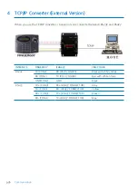
Page 26: ...Stripe RS232 INTERFACE CON2 RS232 TX TXD Black with White Stripe RS232 RX RXD Red with White Stripe Ground GND Black RS422 INTERFACE CON3 RS422 TX TX Yellow RS422 TX TX Gray RS422 RX RX Blue RS422 RX RX Brown TCP IP Communication CON6 TCP IP Communication 8PIN Connector Module I O PORT NAME SIGNAL NAME COLOR CODED 3 Option TCP IP Module Star FINGER007 is able to use TCP IP Communication An optiona...

Page 27: ...Installation Tips Check point 8 p 20 1 Check Points before Installation 1 1 Installation Layout ...

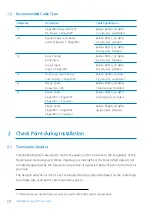
Page 28: ...WG 2 twisted pair shielded RS485 Cable Finger007 Finger007 Finger007 Converter Belden 9829 24 AWG 2 twisted pair shielded RS422 Cable Finger007 Finger007 Finger007 Converter Belden 9830 24 AWG 3wisted pair shielded 2 Check Point during Installation 2 1 Termination Resistor Termination Resistors are used to match impedance of the network to the impedance of the transmission line being used When imp...

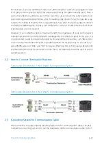
Page 29: ...h the impedance of cable and network is mismatched and the transmitted signal is overlapped by the reflected signal In this case it is recommended to add Termination Resistors to the end of the receiver lines A 120Ω resistor can be used for Termination Resistor in parallel between the receiver lines A and B for 2 wires RS485 system or RX and RX for 4 wires RS422 system A Termination Resistor of l ...

Page 30: ...is current flow will creat e noise and interfere to communications For the good grounding we recommend to connecting only one end of shield wire of com munication cable to Grounding System If you find earth ground nearby then connect one e nd of shield wire to earth ground If you do not have earth ground nearby then find chassis ground and connect one end of shield wire to chassis ground If you do...

Page 31: ...e output relays there will be a high surge voltage created while the inductor is turning on and off If you do not connect Re verse Diode the surge voltage will transfer and damage the electronic circuit of the controll er It is strongly recommended to add a Reverse Diode between the inductor coils to absorb this surge voltage ...

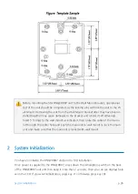
Page 32: ...at which you want to install the unit a nd mark two drilling two Tap 6 32 holes positions and then drill it 2 Drill a 1 2 hole on the center of the wall mount 3 Using two screws install the wall mount to the hall 4 Take out the cable through the center hole 5 After connecting cables initialize the Star FINGER007 And then test basic function Re fer to 8 2 SYSTEM INITIALIZATION 6 Insert O ring at 5 ...

Page 33: ...ings to the wall mount as indicated then route the cable of the main u nit through the center hole and push the main unit to wall mount to lock the main unit and make sure that the main unit is locked with wall mount 2 System Initialization You have to initialize the FINGER007 unit prior to first installation Once power is supplied to the FINGER007 press down the initialization switch on the back ...

Page 34: ... the Product p 27 1 Press the key 1 if you wish to initialize the FINGER007 2 Initialization is progressing 3 Rebooted automatically after Initialization 3 Wiring 3 1 Power Connect wire of DC 12V power to 12V Red wire ...

Page 35: ...wire with Red stripe Connect the other wire NC from the Door Contact Sensor to GND Black wire Auxiliary Input Connection Applied IN1 IN2 Connect one wire from an Auxiliary Input device to one of the IN1 Green wire IN2 Gr een with White stripe Connect the other wire from the Auxiliary Input device to GND Black wire 2 2K Resistance Connection for Cut Off Check You have to connect a 2 2K Resistor bet...

Page 36: ...y 1 Blue with White stripe to wire of Door Lock Device Connect GND Black wire port to wire of Door Lock Devices Door Lock Power Fail Secure Connection Relay 1 Connect COM port of Relay 1 Gray with Red stripe to 12V Red wire Connect NO port of Relay 1 White with Red stripe to wire of Door Lock Device Connect GND Black wire port to wire of Door Lock Devices Alarm Device Connection Relay 2 Connect CO...

Page 37: ... 3 4 Reader Connections External Reader Proximity Reader Connection Connect wire of FINGER007 to 12V Red wire Connect wire of FINGER007 to GND Black wire Connect DATA0 wire of FINGER007 to DATA0 Pink wire Connect DATA1 wire of FINGER007 to DATA1 Cyan wire If the controller and the external reader use separate power sources you must con nect the GND between the controller and the external reader Co...

Page 38: ... p 31 FINGER007SR Standard 34BIT Wiegand Format Proximity Reader Standard 34BIT Wiegand 8BIT Burst Format Proximity and Keypad Reader SR10 SR20 SR30 SRK101 FGR006SR FGR006SRB FINGER007SR Ver A 0 0 or Over Wiegand Output Function ...

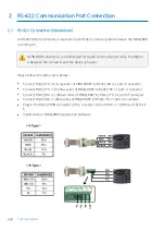
Page 39: ...GER007 to the PIN 2 of the 9 PIN connector Connect RS232 RX Red wire with White stripe port of FINGER007 to the PIN 3 of the 9 PIN connector Connect RS232 GND of FINGER007 to the PIN 5 of the 9 PIN connector Plug in the 9 PIN connector to COM1 or COM2 port of the PC Install and run FINGER007 Application Software The firmware upgrade may not succeed if the distance between the PC and the de vice is...

Page 40: ...verter and the device is too far Please follow the instructions below Connect RS422 TX Gray wire of FINGER007 to RS422 RX port of converter Connect RS422 TX Yellow wire of FINGER007 to RS422 RX port of converter Connect RS422 RX Brown wire of FINGER007 to RS422 TX port of converter Connect RS422 RX Blue wire of FINGER007 to RS422 TX port of converter Plug in the RS232 9PIN connector of the convert...

Page 41: ...nnect one of RS422 port of FINGER007 to RS422 RS232 conver ter I Connect RS422 TX of the one FINGER007 to RX port of the converter II Connect RS422 TX of the one FINGER007 to RX port of the converter III Connect RS422 RX of the one FINGER007 to TX port of the converter IV Connect RS422 RX of the one FINGER007 to TX port of the converter 3 Plug in the RS232 9PIN connector of the converter to the CO...

Page 42: ...between RS232 and RS422 INTERFACE FINGER007 ILAN422 LINE COLOR RS232 TX CON2 RX RS232 DSUB9 Black with White Stripe RX CON2 TX RS232 DSUB9 Red with White Stripe GND CON2 GND Black RS422 TX CON3 RX RS422 CONNECTOR Gray TX CON3 RX RS422 CONNECTOR Yellow RX CON3 TX RS422 CONNECTOR Brown RX CON3 TX RS422 CONNECTOR Blue ...

Page 43: ...tch on the back of the FINGER007 unit and then keep it more than 2 seconds Then the LCD will first display Initialize OK 1 Yes 0 No Press 1 key if you want to initialize the system or 0 to cancel the initialization procedure After all the initialization process is completed the system will be operating in the normal mode and the LCD will display FINGER007 F1 MM DD hh mm ss ...

Page 44: ...e main Setup Menu and you can scroll up or down the menu by pressing the 4 or 6 key If you press the ESC key then the FINGER007 will exit the Setup Mode and return to n ormal operation in Reader Mode 3 Time Date Setting After you enter the Setup Mode you will see the following screen with the current date and time To adjust the time date setting press ENT then enter 15 Digits in a YYYYMMDDh hmmssW...

Page 45: ...No of events and then press ENT again to confirm Prior to changing the maximum number of cardholders you must clear the event data from the memory Because entering the Setup Mode itself generates an event you must always initialize the event memory prior to changing the maximum ID nu mber setting For additional information on how to intialize the event memory re fer to 12 1 9 Event clear If you at...

Page 46: ...registration item appears on the LCD press ENT to b egin the ID registration process For detailed information on the ID registration process please refer to 12 3 1 ID registration How to place your finger onto the scanner when you register card ID When you register or verify your fingerprint please place your finger onto the scan ner correctly as illustrated below ...

Page 47: ...ation is done card ID or authorization status appears on the 3 LCD and fingerprint quality level also appears e g Q3 4 Quality level appears from 1 to 5 In case of Q1 or Q2 you can t use on Identification Mode 1 N because of bad quality In case of Q3 Q4 or Q5 you can use on Identification Mode 1 N because of good qua lity e g In case of fingerprint identification Quality Level 3 Card ID 12300111 1...

Page 48: ...ord is input wrong fingerprint is input ove r the Time Schedule and access wrong door the access is denied and the alarm Relay 2 wi ll be activated for 3 seconds Defaults with RED LED on 2 Default Setting When you operate the FINGER007 first time or you initialize the FINGER007 the controller will setup all values defaults Factory Settings You can change the settings for desired appli cation Pleas...

Page 49: ...Setting Changes 13 p 42 ...

Page 50: ...an move to other setup menus by pressing the F1 key for SETUP MEN U F1 F2 key for SETUP MENU F2 F3 key for SETUP MENU F3 and F4 ke y for SETUP MENU F4 There are setting items in the main setup menu and you c an scroll up or down the menu by pressing the 4 or 6 key If you press the ES C key then the FINGER007 will exit the Setup Mode and return to normal operati on in Reader Mode 1 The default Mast...

Page 51: ...p 44 Setup Menu F1 1 Setup Menu F1 ...

Page 52: ...1 2 Communication Address A communication address is a unique number assigned to each device for communication T he default address is 00 For proper communication with the PC it is important that the value you set here should ma tch the value you set on the application software It is also important to make sure each devi ce on a loop has a unique address To change the communication address of the ...

Page 53: ...etting Troubleshooting Communication Problems Step 1 Match the communication address between the device and the Application Software Step 2 Match the Baud Rate between the device and the Application Software Step 3 Ensure that the COM port setting in the Application Software is correct Step 4 Ensure that the communication settings in the Application Software are as follows 1 Parity Bit None 2 Data...

Page 54: ... the door by presenting their card or entering their ID number and th en verifying their identity by both a fingerprint and a password 1 5 Reader 2 Mode If you have an external reader connected to the FINGER007 referred to herein as Reader 2 you must adjust this setting according to what access mode is used on Reader 2 To change the Access Mode for Reader 2 press ENT select the desired mode by pre...

Page 55: ... and then either enter the desired 8Digit Master ID or present a card to the reader For the FINGER007SR the Master ID is 10Digits long in the range of 0000000000 to 4294967295 On the next screen enter the desired 4Digit Master Password in the PW field and in the FP field enter 0 if you wish to access Setup Mode without master fingerprint verification or 1 if you wish to use master fingerprint in w...

Page 56: ...the device is not needed since it will be deleted after the initialization To initialize the FINGER007 press ENT and then press 1 to confirm If you wish to canc el and exit without initialization press 0 instead 1 8 Card ID Clear Card ID clear allows you to delete all the card data from the FINGER007 To clear the card d ata stored in the memory press ENT and then press 1 to confirm If you wish to ...

Page 57: ...ry make sure you do not need the data stored in the device 1 10 Time Schedule Clear T S Clear allows you to delete all the data related to time scheduling such as Time Schedule s Holiday and Reader Time Schedules Holiday Codes etc To clear the time schedule data st ored in the memory press ENT and then press 1 to confirm If you wish to cancel and e xit press 0 instead Before you clear the time sch...

Page 58: ...Setting Changes p 51 2 Setup Menu F2 ...

Page 59: ...p 52 Setup Menu F2 ...

Page 60: ...e or change an existing one press ENT and the LCD will show T S information such as T S code day ti7me interval and time period Press 2 or 8 to scroll up or down the time schedule code 01 10 and the day of the week Mon Sun and holiday Press 4 or 6 to scroll up or down the time inte rval The holiday in this time schedule will be linked to the holiday schedule code S elect a time schedule code day a...

Page 61: ...to the Software Manual 2 2 Holiday T S You can define up to 10 Holiday T S codes Holiday T S code 00 is the default code without any holidays This means that applying Holiday T S code 00 is the same as applying no holid ays at all You can define Holiday T S codes 01 to 10 Each holiday schedule code can have up to 32 holidays defined ...

Page 62: ...formation please refer to the Software Manual 2 3 Holiday Code The Holiday code setting lets you link a holiday schedule to a time schedule The default holi day schedule code is 00 which means no holidays are applied to the time schedule Use 4 or 6 to scroll up or down from the T S code 01 to 10 and press ENT Then ent er a 2Digit holiday schedule code and press ENT to store the changed settings to...

Page 63: ...See 1 1 Time Setting 3 Here in Reader T S press ENT enter the 2Digit T S code In this case 01 and then p ress ENT again to confirm 4 To return to the previous menu press ESC 2 5 Input Output Definition In Output Define allows you to adjust In Output settings Output activation time In Output Time Schedule Cut Off Check etc To change the In Output Settings press ENT and select an item using 4 or 6 k...

Page 64: ...the output signal time for when access is granted following a duress event When a particular event occurs the FINGER007 will generate an output signal for Relays 1 and 2 TTL 1 and 2 and Buzzer for the length of time defined for eac h 2 6 Output Time Setting Output Time Set allows you to define the unit of time 1 sec Output Time is calculated in the time unit of 1 second for the In Output definitio...

Page 65: ... 1 DR for 0 5 seconds The Time Unit should be set to 0 1 SEC The Door Relay DR Output Time should be set to 05 PUT TIME to 1 sec 2 7 Anti Passback The Anti Pass Back feature is used to prevent an identical user from entering or exiting the d oor more than twice in a row so that employees cannot pass back their cards to their cowor kers Anti Pass Back can be applied only when an Exit Reader is inst...

Page 66: ...lt PIN Input is disabled If you choose Disable you cannot gain access via password input when using RF PW mode 2 9 Event Alarm Event Alarm allows you to decide whether to enable or disable the event memory full alarm If you enable Event Alarm the FINGER007 beeps with an alarm message when the event me mory becomes more than 90 full To enable or disable Event Alarm press ENT and press 4 or 6 to sel...

Page 67: ...rent DURESS PASSWORD To change the password press ENT and enter the desired 2 Digit Duress Password and press ENT again to confirm If you do not wish to ch ange the password press ESC In case of duress enter the 2Digit Duress Password and press ENT prior to the r egular access process Following a successful access process access will be granted as usual but at the same time a duress alarm will be ...

Page 68: ...Rela y Time 01 98 Delay 01 98 sec will be inserted before an alarm is activated 99 No alarm After entering the number press ENT to confirm For this application a Door Contact Sensor must be installed on the door 2 12 LCD Display LCD DISPLAY allows you to decide whether to display the card number or the status messag e on the LCD when access is granted or denied To change the setting press ENT and ...

Page 69: ...and press ENT to confirm The buzzer beeps regardless of this setting when you exit the Setup Mode when a memory alarm is activated or when Buzzer Output is defined in In Output Defin e 2 14 TTL WEIGAND Output This function allows whether to use TTL Output as WEIGAND Output The default value is NOT USE You can select setup status by using 4 or 6 keys If you press ENTER after choosing TTL WEIGAND to...

Page 70: ...format smart cards To do so you must change the D ata BYTE setting to 2BYTE To change the setting press ENT and press 4 or 6 to sel ect 4BYTE or 2BYTE and press ENT to confirm 4 Byte Default The Card Number can be in the ranges of 00000000 4294967295 2 Byte The first and last 5 digits can each be in the ranges of 00000 65535 respectively The total is in the ranges of 0000000000 6553565535 ...

Page 71: ...p 64 Setup Menu F3 3 Setup Menu F3 ...

Page 72: ...umber ID vi a the keypad and press ENT A Card Number ID can be 4 to 8Digits long For the FINGER007SR it can be 4 to 10Digits long Once the Card Number is entered enter the Password PW Time Schedule TS Reader Nu mber RD and Use of Fingerprint FP and press ENT For more information see below If you have entered 1 in the FP field the fingerprint scanner will be lit up Then place the ca rdholder s fing...

Page 73: ...assword verification can be enabled in 11 1 4 Reader1 Mode This field is compulsory even if you do not use password verification TS Time Schedule If you wish to apply a certain time schedule to the cardholder enter the T S code If y ou wish to allow the cardholder round the clock access enter 0 RD Reader Assignment Code To use both Readers1 and 2 for the cardholder Enter 0 or 3 To use just Reader1...

Page 74: ...you presented or the card number you entered is not found the UNREGIS TERED ID message will be displayed 3 3 ID List ID List allows you to search for a certain registered card or view the list of all registered cards To begin press ENT To search for a certain registered card press 1 To view the entire list of all registered card s press 2 If you have entered 1 enter the Card Number ID or present t...

Page 75: ...stered ID Count The number of registered user IDs is displayed This count automatically increases or decreas es as IDs are registered or deleted The LCD above shows that the total of 1234 user IDs are registered in the memory 3 5 ID Memory ID Memory allows you to decide how to divide the memory space between IDs and event tra nsactions The total number of IDs and event transactions combined is a m...

Page 76: ...ory the LCD will display the ID TOTAL COUNT WRON G error message 3 6 Event List Event List allows you to check the past access events with the information such as card num ber time and date etc The LCD displays the information of the access events as follows Card Number ID Reader Number R 1 Reader 1 Event Date YY MM DD Day of the Week 4 Wed Time hh m m ss Access Status 0 Access granted and Functio...

Page 77: ... of event transactions is displayed This count automatically increases or decreas es as new events occur or the existing events are uploaded to the PC The LCD on the left sh ows that the totals of 12345 event transactions are stored in the memory ...

Page 78: ...Setting Changes p 71 4 Setup Menu F4 ...

Page 79: ...p 72 Setup Menu F4 ...

Page 80: ...he memory of the FINGER007 To begin the test press EN T If the test is successful the LCD will display the TEST PASSED message Press any key to fini sh the test If the test is unsuccessful the LCD will display the TEST FAILED message Press any key to finish the test and try again If the problem persists please contact your local IDTE CK dealer for assistance or service ...

Page 81: ...activated and you will hear Tick Tack sounds with the green LED blinking twice Second output oorts3 and 4 will be tested During the test TTL outputs are activated and the yellow LED blinks twice Yo u can check the voltage level of the TTL outputs with appropriate test equipment Lastly out put port 5 will be tested During the test you will hear 2 beeps After all the tests are over p ress any key to...

Page 82: ...h the display of the firmware upda te date YYYY MM DD After the test is finished press any key to exit Letter A corresponds to ESC B to ENT C to F1 D to F2 E to F3 and F to F4 4 5 Keypad Test Keypad Test allows you to test the keys on the keypad To begin the test press ENT Press each key on the keypad then the number or letter that corresponds to the key pressed will disappear from the screen Afte...

Page 83: ...the LCD will display the reader number and the card number After the test is finished press ESC to exit Reader 1 refers to the built in reader of the FINGER007 and Reader 2 refers to an external reader You can also use Reader Test to check the number of a card 4 7 Input DIP Switch Test Input Test allows you to check the status of Input Ports and DIP switches Communication A ddress Setting Switches...

Page 84: ...FF Disabled 1 ON Enabled If you activate the Cut Off Check feature for all the input ports in 5 IN OUT DEFIN E from F2 Setup menu the result of an input port test will change to 222200 If t ermination resistors are not connected or 000000 If termination resistors are con nected 4 8 Communication Test COMM Test allows you to test communication Prior to the test connect the RS232 RX wire Black wire ...

Page 85: ...on without having to present their cards or enter their ID numbers If this feature is enabled a user can j ust place the fingerprint onto the fingerprint scanner and then the FINGER007 will perform 1 N authentication for the entire fingerprint templates in the database and grant access if a fingerprint template that matches the user s fingerprint is found 4 10 Dual Fingerprint Mode The Dual Finger...

Page 86: ...uccessful authentication However t he authentication process may take longer with this feature on To enable or disable the Adaptive Mode press ENT and press 4 or 6 to select ENABL E or DISABLE and press ENT to confirm 4 12 FP STATUS FP Status is a special feature designed for special environments where the fingers of most e mployees might be too dry or wet If you set the FP Status setting to dry o...

Page 87: ...ALITY Register Quality and Verify Quality are the threshold values for fingerprint image capture in t he fingerprint registration enrollment process Register Quality and verification process Ver ify Quality If the quality value for a capture fingerprint image is below the Register Quality t hreshold the authentication registration or verification is rejected By adjusting the thresh old value you c...

Page 88: ...INGER007 and ho w many can be registered in total Depending on the specification of the fingerprint module in use the total fingerprint capacity can be 1000 2000 or 4000 fingerprints 4 18 Fingerprint Module Test FP Test allows you to test the fingerprint module on your FINGER007 To begin the test pres s ENT If the test is successful the TEST PASSED message will be displayed If the test is u nsucce...

Page 89: ...p 82 Setup Menu F4 4 19 Fingerprint Device Information Check Device Info shows you the model name of the fingerprint module on your FINGER007 ...

Page 90: ...t Limit NOT USE 5 Use of Event Memory USE 6 Unit of Time for Output Ports UNIT 1 SEC 7 Application Mode to Output Port Time Schedules NOT USE 8 Anti Pass Back Feature NOT USE 9 Duress Mode NOT USE 10 Door Open Alarm Time 03 11 Time Schedule All Time 00 00 12 Holiday All Date 00 00 13 Holiday Code 00 All holiday codes 14 Time Schedule Assigned to Reader 1 Mode 00 15 Time Schedule Assigned to Reader...

Page 91: ...0 00 00 10 Reader 2 ID OK 03 00 00 00 00 11 Reader 2 ID Error 00 03 00 00 00 12 Reader 2 ID T S Error 00 03 00 00 00 13 Reader 2 APB Error 00 03 00 00 00 14 DURESS MODE 03 00 00 00 00 15 OUTPUT TIME SCHEDULE 00 00 00 00 00 16 INPUT TIME SCHEDULE Input 1 Input 2 Input 3 Input 4 Input 5 00 00 00 00 00 17 DR OPEN ALARM Relay 1 Relay 2 TTL 1 TTL 2 BUZZER 00 03 00 00 00 18 CUT OFF ALARM Input 1 Input 2...

Page 92: ...enote Operating time is not limited Index No 15 The values indicate the Time Schedule Code index applied to each output Index No 16 The values indicate the Time Schedule Code index applied to each input Index No 19 21 The values indicate whether to enable or disable the feature for each output 01 Enable 00 Disable ...

Page 93: ...MASTER ID 5 5 The device work well with RF Card but does not work when inputting card number 6 6 A buzzer keeps making sounds Bee Bee Bee 7 7 A buzzer keeps making sounds Bee 8 8 SCHEDULE ERROR appears on the LCD when a card is read 9 9 ACCESS DOOR ERR appears on the LCD when a card is read 10 10 I want to access with card only without password 11 11 I want to access with fingerprint only without ...

Page 94: ...ommunication ID is good Check communication address setting of software and the device 1 Check if communication ID set in the device is same with communication ID set in a soft ware See Setting Changes Setup Menu F1 COMMUNICATION address and check a c ommunication address set in the device 2 When you use several devices together communication addresses set in the devices sh ould be different from ...

Page 95: ... device 2 1 The ID of the card may not be registered to software 1 Check if the ID is registered to software 2 If the ID is not registered register the ID to the software and execute batch transmissio n of the IDs from software to the device If the problem persists please contact service center 3 When configuring the device using MASTER ID sudde nly the device goes back to the normal mode 3 1 If y...

Page 96: ...device Once you initialize the device MASTER ID of the device goes back to 00000000 8 digits In the case of SR model MASTER ID goes back to 0000000000 10 digits If the problem persists please contact service center 5 The device work well with RF Card but does not work when inputting card number 5 1 Please check if Keypad is set to USE The default of the keypad input is NOT USE 1 See Setting Change...

Page 97: ...s making sounds Bee 7 1 Check if the tamper switch is pressed well The device has a tamper switch on the back to check if the device is fixed on the wall we ll The tamper switch should be being pressed when and after the installation If the switch is not pressed tamper alarm is activated and the buzzer sounds an alarm The tamper switch let you know when someone has taken the device off the wall wh...

Page 98: ... it to what you want If you cannot change it from the software from the device see Setting Changes SETUP MENU F3 ID Deletion of the manual and delete the ID and see Setting Changes SETUP MENU F3 ID Registration of the manual to newly create the I D with the right time schedule To let a user access anytime set time schedule to 00 If the problem persists please contact service center 9 ACCESS DOOR E...

Page 99: ... 2 Exit Reader then the the device g enerates an error message Access Door Error on the LCD display If the problem persists please contact service center 10 I want to access with card only without password 10 1 Please check reader mode set for the ID By changing reader mode you can select how to authenticate when accessing See Setting Changes SETUP MENU F1 Reader 1 Mode of the manual and select ho...

Page 100: ...ssword 11 1 Please check if IDENTIFICATION mode is set to USE See Setting Changes SETUP MENU F4 Identification Mode of the manual and set ID ENTIFICATION MODE to USE If the problem persists please contact service center 12 A fingerprint is not recognized 12 1 Please check the status of the fingerprint If something is attached to fingerprint fingerprint recognition may not work properly Remove it I...

Page 101: ...blem persists please contact service center 13 I want to register 2 fingerprints for 1 ID 13 1 Please check if Dual Fingerprint Mode is set to USE If you use Dual Fingerprint Mode you can register 2 fingerprints for 1 ID just in case a finger print is injured 1 See Setting Changes SETUP MENU F4 Dual Fingerprint Mode of the manual an d check if Dual Fingerprint mode is set to USE 2 If it is not set...

Page 102: ... including interference that may caus e undesired operation This equipment has been tested and found to comply with the limits for a Class A Digital De vice pursuant to Part 15 of the FCC rules These limits are designed to this equipment gener ates uses and can radiate radio frequency energy and if not installed and used in accordan ce with the instructions may cause harmful interference to radio ...

Page 103: ...g Gangseo Gu Seoul 157 030 Korea Tel 82 2 2659 0055 Fax 82 2 2659 0086 E mail webmaster idteck com Website www idteck com E Training Center http www idtecktraining com IDTECK Production Facility and RMA Center 2F 89 4Dodang Dong Weonmi Gu Bucheon Si Gyeonggi Do 420 130 Korea Tel 82 2 2659 0055 Fax 82 2 2659 0086 E mail webmaster idteck com Website www idteck com E Training Center http www idtecktr...

Reviews: