background image


User’s Manual 


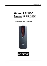
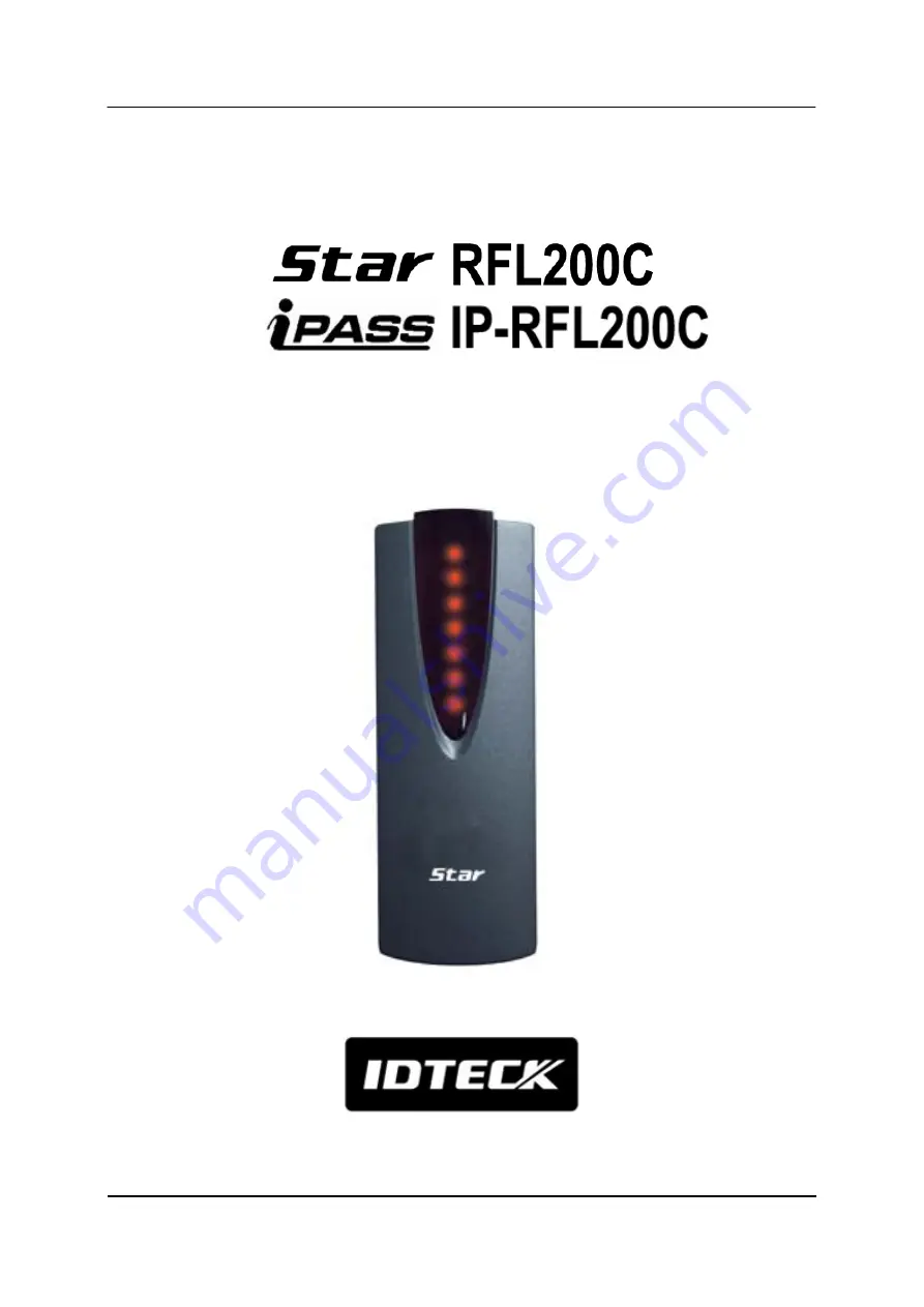
Proximity Access Controller 


Summary of Contents for iPASS IP-RFL200C

Page 1: ...User s Manual Proximity Access Controller ...

Page 2: ... 4 Identifying Supplied Parts 4 5 Specification 5 6 Installation 6 7 Color Coded Wiring Table 7 8 Wire Connection to Controller 7 11 Operation 12 12 FCC Registration Information 14 13 Warranty Policy and Limitation of Liability 15 14 How to Make RMA Request After Sales Service 16 ...

Page 3: ...he covers may expose you to dangerous voltages or other risks Also incorrect reassembly can cause electric shock when the unit is subsequently used 8 Unplug this product from the Direct Current DC power source and refer to qualified service personnel under these conditions a When the power supply cord or plug is damaged or frayed b If liquid has been spilled on the product c If the product does no...

Page 4: ...s e g Bluetooth module required optional 512 Users 256 Event Buffers Direct Control of Door Lock Power Fail Safe or Power Fail Secure Locks Selectable Solid Epoxy Potted Waterproof Warranty Life Time Compatible Software STAR RFL200C 4 Identifying Supplied Parts Please unpack and check the contents of the box Reader Module RFL200C IP RFL200C User s Manual Bezel 1ea 1ea 1copy 3 5 40 Screw 3 5 25 Scr...

Page 5: ...1 99sec Selectable Power Current DC 12V Max 150mA Communication RS485 Max 255ch Input Port 3ea Exit Button Door Sensor Aux 1 Output Port 2ea TR Output open collector output Rating Max 300mAAlarm Output 1A Lock Output LED Indicator Beeper 9 Array LED Indicators Red and Green Piezo Buzzer Operating Temperature Controller 35 to 60 C 31 to 140 F RF Reader 35 to 65 C 31 to 149 F Operating Humidity 10 t...

Page 6: ...ule through the central hole 6 2 Drill one 0 39 10mm in right horizontal and 1 74 44 4mm in upper vertical through the central hole And drill the other 0 33 8 5mm in left horizontal and 1 59 40 6mm in under vertical through the central hole 6 3 Push reader module on mullion or wall mount then install the main unit using two 6 32 or M3 screws ...

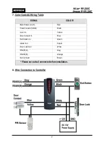
Page 7: ...ntroller SIGNAL COLOR Main Power 12V Red Power Ground GND Black Aux In 1 Yellow Door Contact In Blue Exit Button In Green Alarm Out Purple Door Lock Out White RS485 A Gray RS485 B Orange Not Connect Brown Please cut out tail connector before installation ...

Page 8: ...input Connect NO terminal of door sensor to GND of power supply 8 5 Connecting a door lock type In a power fail safe connect GND wire of power supply to Yellow wire of door lock type input In a power fail secure put a floating state on Yellow wire of door lock type input 8 6 RS485 Communication port connection The INC300 for RS485 RS232 converter is required to connect a product to the PC Connect ...

Page 9: ...You can install up to 255 Units of RFL200C IP RFL200C as in the below figure Max 255 units Board ID 1 255 can be installed in a loop Able to connect directly via RS485 or RS232 converter 485 Converter RFL200C IP RFL200C 485 Orange wire 485 Gray wire ...

Page 10: ...rmal Mode or Toggle Mode Click Save and then Transmit button if finishing to step 10 2 Set In Out Point Choose Door Open Time sec of 1 to 99sec Choose Lock Type one whether Power Fail Safe or Power Fail Secure If clicking Save button one door among System Door Address is checked Click Transmit button SELECT RFL200C DOOR OPEN TIME sec 1 99 sec POWER FAIL SAFE POWER FAIL SECURE RFL200C BOARD ID DOOR...

Page 11: ... CARD DATA and EMPLOYEE INFORMATION Click Save and then Transmit button 10 4 System Initialization StarRFL200C iPASS IP RFL200C is initialized by the software 10 5 LED Color Control The Star RFL200C iPASS IP RFL200C can change its LED color to red or green by the application software INPUT CARD DATA EMPLOYEE INFORMATION SELECT RFL200C ...

Page 12: ...tom After all LEDs are off they turn on red again The door opens for a predefined length of time and the first two LEDS from the top turn red indicating the open status of the door The RFL200C IP RFL200C beeps once 11 3 When an unregistered tag is read on the RFL200C IP RFL200C All LEDs are lit red then they flash on and off twice and stay on The RFL200C IP RFL200C beeps twice 11 4 When a tag is r...

Page 13: ...off Then green LEDs are lit sequentially from bottom to top All LEDs turn green The RFL200C IP RFL200C beeps four times indicating the completion of initialization After initialization is finished return the white green and yellow wires to their original positions Power on the RFL200C IP RFL200C again and it will operate normally again 11 7 Besides the operations described above users can register...

Page 14: ...uant to Part 15 of the FCC Rules These limits are designed to this equipment generates uses and can radiate radio frequency energy and if not installed and used in accordance with the instructions may cause harmful interference to radio communications However there is no guarantee that interference will not occur in a particular installation If this equipment does cause harmful interference to rad...

Page 15: ...TECK does not and cannot know who is present what property is located where this product will be used it would be extremely difficult to determine the actual damages that may result from a failure of the product to perform as anticipated and the low price of this product is based upon the nature of the product provided and the limited liability that IDTECK assumes IDTECK IS NOT RESPONSIBLE FOR ANY...

Page 16: ...the product along with the RAM Code and send it to IDTECK RMA Center Product without RMA Code is not accepted If you have any questions or problems regarding the RMA services please contact us using the following contact information below Friendly representatives at IDTECK are always standing by to provide the best after sales services IDTECK Headquarter 5F Ace Techno Tower B D 684 1 Deungchon Don...

Page 17: ...td The specifications contained in this manual are subject to change without notice at any time 5F Ace Techno Tower B D 684 1 Deungchon Dong Gangseo Gu Seoul 157 030 Korea Tel 82 2 2659 0055 Fax 82 2 2659 0086 E mail webmaster idteck com ...

Reviews: