9
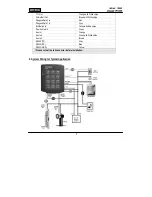
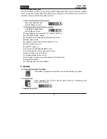
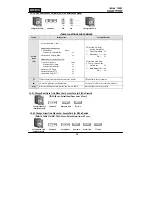
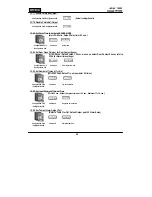
9-8. Wiegand Input Connection from another Compatible Wiegand Reader
(Separate Purchase)
- Connect (+) wire of Reader to DC +12V (be sure that the existing power supply has enough capacity to support
this accessory or upgrade to a sufficient one.)
- Connect (-) wire of Reader to Power GND (-) wire.
- Connect Wiegand output DATA0 wire of the additional Reader to DATA0, Pink wire.
- Connect Wiegand output DATA1 wire of the additional Reader to DATA1, Cyan wire.
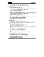
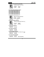
9-9
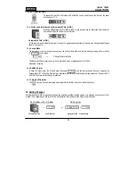
. RS-232 Communication Port Connection
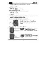
A 9-pin connector (COM Port, female) is required for RS-232 communication between the 100W and a PC.
- Connect RS-232-TX, Grey wire of Main Unit to pin number 2 of 9-pin connector.
- Connect RS-232-RX, Blue wire of Main Unit to pin number 3 of 9-pin connector.
- Connect RS-232-GND, Yellow wire of Main Unit to pin number 5 of 9-pin connector.
- Plug in 9-pin connector to COM1 or COM2 Port of the PC.
- Install and run STAR 100R PRO Application Software.
9-10. Chime Bell Connection
(Separate purchase required)
- Connect (+) wire of Chime Bell unit to Bell Output, Brown/White wire of Main Unit.
- Connect (-) wire of Chime Bell unit to Power GND (-) wire.
10. Initial Setup
The Flash memory of each shipped STAR 100W contains a minimum set of default values, but it does not have any
other preprogrammed values or user’s data in it, therefore, Initial Setup is required upon the first time the unit is
powered-up in order to operate the unit properly.
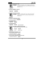
10-1. Registration of RF Cards for RF CARD ONLY MODE
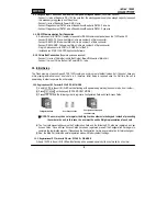
(1) Apply 12VDC to the unit. All 3 LEDs will be flashing with a powered-up melody (do mi sol me do, do mi sol do~).
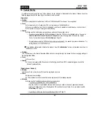
(2) Press on the keypad. (RF CARD ONLY MODE )
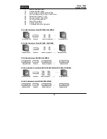
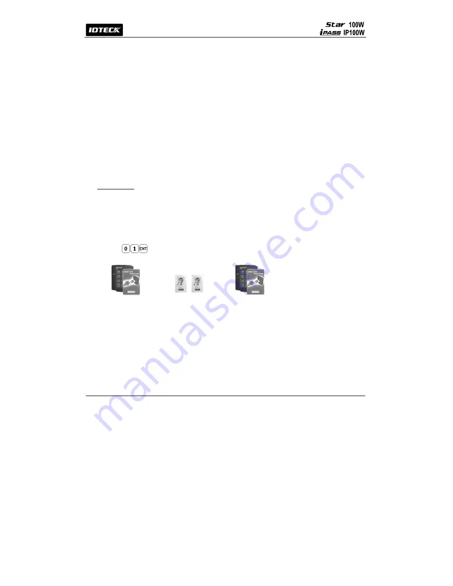
(3) Present RF Cards in the following order to register a Configuration Card and User Access Cards.
Configuration Card User Access Cards
※
NOTE: The user may choose to register the 8-digit card numbers via the keypad instead of presenting
the cards to the unit; In this case, the user must know the 8-digit representation of each card.
(4) The first card presented becomes the Configuration Card and the following RF Cards are registered as User
Access Cards. Once all User Access Cards have been registered, present the Configuration Card again to
complete the registration process. (Please keep the Configuration Card in a secure location for future changes.)
(5) Now, the Main Unit enters the normal operation mode with factory default settings.
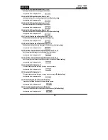
10-2. Registration of RF Cards with PINs for RF CARD + PIN MODE
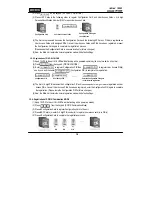
(1) Apply 12VDC to the unit. All 3 LEDs will be flashing with a powered-up melody (do mi sol me do, do mi sol do~).
Configuration Card again
to end the task
Summary of Contents for iPass IP100W
Page 1: ...User s Manual ...
Page 31: ...31 17 Template MEMO ...


