background image


41  

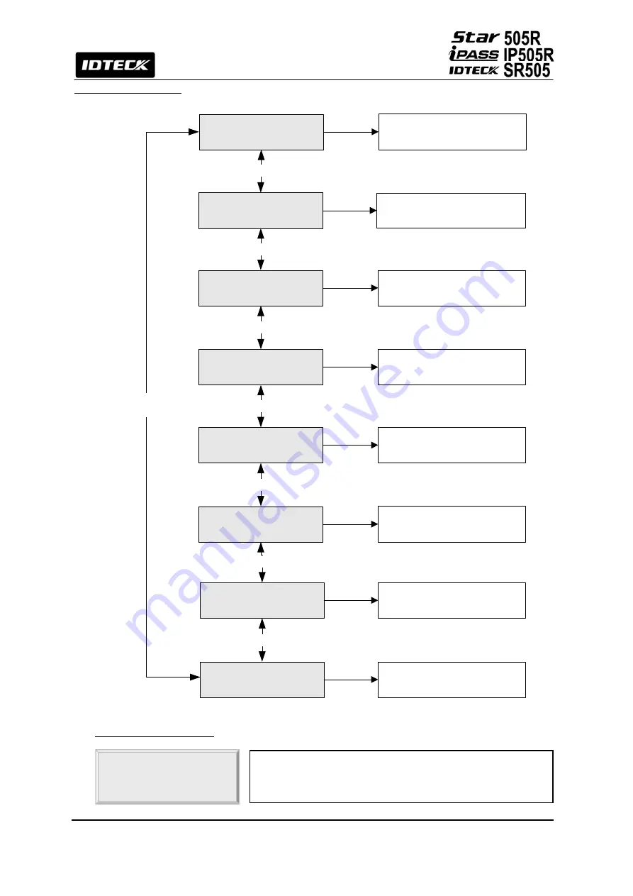
12.4 SETUP MENU F4


12.4.1 VERSION CHECK


VERSION 

505R: V5.0 

. The version of the controller’s firmware is displayed on 

the LCD. Press <4> or <6> key to look for other menus 
of setup menu F4.

 VERSION

SRAM TEST

OUTPUT TEST

LCD TEST

DISPLAY CURRENT F/W 

VERSION

KEYPAD TEST

key<4> or <6>

key<4> or <6>

key<4> or <6>

key<4> or <6>

SEARCHING KEY 

<4> or <6>

SRAM TEST

OUTPUT TEST

LCD TEST

KEYPAD TEST

READER TEST

READER TEST

INPUT TEST

INPUT TEST

COMM TEST

COMMUNICATION TEST

(RS-232)

key<4> or <6>

key<4> or <6>

key<4> or <6>

Summary of Contents for PASS IP505R

Page 1: ...User s Manual Proximity PIN Time Attendance Access Controller ...

Page 2: ...5 Identifying Supplied Parts 5 6 Product Overview 6 7 Installation Checkpoint Tips 9 8 Installation 12 9 Communications 16 10 Basic Settings 19 11 Operations 23 12 Setting Changes 23 13 Appendix 45 14 FCC Registration Information 50 15 Warranty Policy and Limitation of Liability 51 16 Template 53 ...

Page 3: ...ting instructions in this manual Improper adjustment of other controls that are not covered by this manual may damage the unit and will often require extensive work by a qualified technician to restore normal operation d If the product exhibits a distinct change in performance 2 General The Star 505R is a highly advanced intelligent single door controller with a dual 8bit microprocessor to meet th...

Page 4: ...N Converter Required 1ea of External Reader Port for Anti Pass Back 26bit Wiegand and 4 8bit Burst for PIN Duress Mode Function Independent 4 Inputs and 4 Outputs Including 2 Form C Relay Outputs Dual Tamper Switches Alarm Event Monitoring using Tamper Switch by Application Software Compatible Software STARWATCH DUAL PRO I II Comparison Table Built in 125KHz 4 Proximity Reader 505R RF Only PIN 4 6...

Page 5: ...x 0 55 65 6mm x 13 8mm Screen Keypad 16 Key Numeric Keypad with Back Lighting LED Indicator 4 Array LED Indicators Red Green and Yellow Beeper Piezo Buzzer LCD 0 to 50 C 32 to 122 F Controller 0 to 70 C 32 to 158 F Operating Temperature RF Reader 35 to 65 C 31 to 149 F Operating Humidity 10 to 90 relative humidity non condensing Color Material Dark Pearl Gray Polycarbonate Dimension W x H x T 150m...

Page 6: ...e user can not enter twice with the entry card without properly using the exit before Input Output The Star 505R has 4 built in inputs and 4 outputs 2 relay outputs and 2 TTL outputs which can be used to manipulate a wide variety of controls Time Schedule Setup You can program 10 time schedules and apply one time schedule to each User Each time schedule has 8 different time zones from Monday Sunda...

Page 7: ...larm event will be sent to the host PC 6 2 Product Explanation 6 2 1 Front Panel Description Figure Description of Star 505R Front Panel Figure Description of Star 505R Back Panel LCD Module LCD module display 505R status System Operation Status LED When the power is applied to 505R the red LED is turned on When the Relay 1 is operated the green LED is turned on When the Relay 2 is operated the ye...

Page 8: ... Door Relay Out COM Gray with Red stripe Door Relay Out NC Blue with White stripe Door Relay Out NO White with Red stripe Alarm Relay Out COM White Alarm Relay Out NC Purple with White stripe Alarm Relay Out NO Purple TTL Out 1 Orange with White stripe TTL Out 2 Brown with White stripe Exit Button In Orange Door Contact In Yellow with Red stripe Aux In 1 Green Aux In 2 Green with White stripe Wieg...

Page 9: ...S BEFORE INSTALLATION 7 1 1 SELECTION OF CABLE System installation cabling will be configured as follow Figure System Installation Layout 7 1 2 RECOMMENDED CABLE TYPE AND PERMISSIBLE LENGTH OF CABLE Reference Description Cable Specification Maximum Distance 505R Power DC12V DC Power 505R Belden 9409 18 AWG 2 conductor unshielded 30m Belden 9512 22 AWG 4 conductor shielded Reader Power and Data Ext...

Page 10: ...aud rate and 1 200m length of cable the propagation velocity of cable is 0 66 x speed of light This value is specified by the cable manufacturer if we assume the reflections will damp out in three round trip up and down the cable length the transmitted signal will stabilize 18 6us after the leading edge of a bit Since the data bit is captured in the middle of the bit which is approximately 52us af...

Page 11: ... a current flow through the shield wire when the voltage level of both ends of shield wire is not equal and this current flow will create noise and interfere to communications For the good grounding we recommend to connecting ONLY one end of shield wire of communication cable to grounding system If you find earth ground nearby then connect one end of shield wire to earth ground If you do not have ...

Page 12: ...reverse diode between the inductor coils to absorb this surge voltage Figure Reverse Diode connection 8 Installation 8 1 DIMENSIONS Unit mm inch 150mm 5 9 x 120mm 4 72 x 39 5mm 1 55 8 2 BACKUP BATTERY DIP SWITCH Star 505R has a switch for the backup battery connection which remains open circuit to prevent any current consumption of the backup battery Figure Switch setting Before the Star 505R oper...

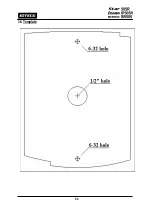
Page 13: ...RODUCT 8 4 1 Tear off page 56 and use the provided template to drill two 6 32 holes and one 1 2 hole on the proper location of the wall to mount the Wall Mount bracket as shown below Skip this step if the gang box is already installed on the wall Power on Initialize Com Turn OFF Power Power off System initialization completion If you turn on the system power after connected 3 wires pink cyan and b...

Page 14: ... of DC 12V power to the Black wire 8 5 2 INPUT CONNECTIONS Exit Button Connection Connect one wire from an Exit Button to the Orange wire Connect the other wire from the Exit Button to the GND Door Contact Sensor Connection Connect one wire from a Door Contact Sensor to the Yellow wire with Red stripe Connect the other wire from the Door Contact Sensor to GND Auxiliary Input Connection Applied to ...

Page 15: ...E current Min 1A 1N4001 1N4007 or similar 8 5 4 EXTRA READER CONNECTIONS Proximity Reader Connection 1 Connect wire of the Proximity Reader to DC 12V 2 Connect wire of the Proximity Reader to GND of Power 3 Connect Data 0 wire of the Proximity Reader to D0 the Pink wire 4 Connect Data 1 wire of the Proximity Reader to D1 the Cyan wire Compatible Readers 505R iP 505R Standard 26bit Wiegand Format P...

Page 16: ...rt of the host PC 5 Install and run 505R Application Software Figure RS232 COMMUNICATON 9 2 RS 422 COMMUNICATION PORT CONNECTION 9 2 1 RS 422 CONNECTION STAND ALONE RS422 RS232 converter CNP200 is required to use RS422 communication between the 505R and a host computer Please follow the instructions 1 Connect RS422 TX Yellow wire of the 505R to RS422 RX port of the converter 2 Connect RS422 TX Gre...

Page 17: ...2 TX Grey wire of another 505R 3 Connect RS422 RX Blue wire of one 505R to RS422 RX Blue wire of another 505R 4 Connect RS422 RX Brown wire of one 505R to RS422 RX Brown wire of another 505R Second you have to connect one of RS422 port of 505R to RS422 RS232 converter 1 Connect RS422 TX Yellow wire of the one 505R to RX port of the converter 2 Connect RS422 TX Grey wire of the one 505R to RX port ...

Page 18: ...18 Figure RS 422 Communication between 505Rs and Host Computer 9 3 DIAL UP MODEM Please read the Software manual 9 4 TCP IP CONVERTER EXTERNAL VERSION Please read the Software manual ...

Page 19: ... to another SETUP MENU by pressing the F1 key for SETUP MENU F1 F2 key for SETUP MENU F2 F3 key for SETUP MENU F3 and F4 key for SETUP MENU F4 There are several SUBMENUS in the main SETUP MENU and you can scroll up and down the SUBMENU by pressing 4 and 6 key in the main SETUP MENU If you don t press any key for 60 seconds or if you press the ESC key 505R will exit the SETUP MENU and return to nor...

Page 20: ...e registered into 505R and if you setup less ID COUNT 505R will increase the EVENT Buffer size to maximum The default ID COUNT is 5 000 Users and the default EVENT Buffer size is 5 000 It can be stored when you operate 505R off line Select ID COUNT in the SETUP MENU F3 then setup the maximum User IDs to be registered into 505R Follow the steps to setup the ID COUNT The Master ID for SR505 is a ten...

Page 21: ...the User ID into the 505R Select SETUP MENU F3 ID REGISTRATION and follow the steps below For 505R or IP505R registration can be done either with RF cards or via keypad input depending on the Reader 1 Mode setting The Master ID for SR505 is a ten digit number Default setting 0000000000 This step appears only on SR505 1 Registration by RF Cards Applicable if 1 Card is selected on SR505 or if Reader...

Page 22: ...05R this field does not appear during registration via the keypad 4 TS TS is the Time Schedule code 00 10 TS is the Time Schedule for the Reader 1 Reader 2 When you present the card to a Reader the cardholder is only allowed the access of the door during the Time Schedule code entered to TS__ To control the accessible Time Schedule for each cardholder you must setup the Time schedules first and en...

Page 23: ...alue defaults factory settings You can change the settings for the desired application Please refer to the APPENDIX for the default setting values 12 Setting Changes INITIAL DISPLAY MODEL NAME CURRENT TIME ID INPUT MASTER ID YES YES NO OPERATE GENERAL MODE SETUP MODE NO SETUP F1 MODE SETUP F2 MODE 1 TIME SCHEDULE 2 HOLIDAY SETTING 3 IN OUT DEFINE 4 HOLIDAY INDEX 5 MODE INDEX 6 LCD DISPLAY 7 OUTPUT...

Page 24: ... up and down the SUB MENU by pressing the 4 and 6 key in the main SETUP MENU If you don t press any key for 60 seconds or if you press ESC key 505R will exit the SETUP MENU and return to normal operation In the case of SR505 Press ten times the 0 key Default setting 0000000000 to enter the SETUP MENU 12 1 SETUP MENU F1 READER 2 MODE RF P W PassWord TIME SETTING APB SETUP NOT USE DEFAULT USE RF Onl...

Page 25: ...IN_INPUT ENABLE DISABLE DEFAULT key 4 or 6 EVENT MEMORY NOT USE USE DEFAULT key 4 or 6 key 4 or 6 key 4 or 6 SEARCHING KEY 4 or 6 SYSTEM INITIALIZE YES NO CARD ID CLEAR YES NO key 4 or 6 key 4 or 6 FUNCTION KEY NOT USE DEFAULT USE key 4 or 6 DATA BYTE TYPE 2BYTE 4BYTE DEFAULT key 4 or 6 ...

Page 26: ...he door is accessible with the proximity card alone RF PW The door is accessible with the proximity card and Password PIN ONLY The door is accessible with the PIN number 4 6 digits If you select PIN it will be affected to Reader 1 and 2 APB SETUP NOT USE It shows anti pass back operation is not in use Press ENT key It only applies when the door has an Exit Reader TIME SETTING YYYYMMDDhhmmssW _____...

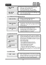
Page 27: ...M ID of iCON100 and host PC Check BAUD RATE of iCON100 and host PC Check communication port and cable Check COM port setup of host PC Parity None Data Bit 8 bit Stop Bit 1 bit To change the baud rate press ENT key and select desired baud rate by pressing 4 or 6 key then press ENT key EVENT CLEAR When the event memory is full or when you want to change ID COUNT you can clear the event memory in thi...

Page 28: ...is registered in the controller by RF cards or through the keypad For RF cards Press 1 key the keypad 2 key or you can quit the registration by pressing ESC key MASTER ID CHANGE ________ The reader is waiting for an RF card which is to be registered The card number will appear with a beep as the card is read After recognition the next message will appear XXXXXXXX ____ Registered This figure appear...

Page 29: ...User IDs from the memory Press ENT key then press the 1 key to clear all User IDs or 0 key to cancel the operation CAUTION Before clearing all User IDs make sure that the registered User ID is no longer used otherwise you may lose all registered User IDs When you want to delete all Time Schedules 01 15 you can clear them from the memory Press ENT key and press the 1 key to clear all T S or 0 key t...

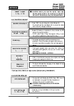
Page 30: ...sword and press ENT key Afterwards present the card Door will be opened as normal but the Duress alarm will be generated and reported to the host PC DURESS MODE SET NOT USE DURESS MODE SET USE DURESS P W 00 FUNCTION KEY NOT USE FUNCTION KEY NOT USE The User can decide what will be shown on display matched with Function key Default value for FUNCTION KEY is NOT USE and set USE in order to apply FUN...

Page 31: ...he value matched with Function key will be shown on certain time when function key is pressed WAIT TIME Time duration between the display of value matched with function to display OK default DATA BYTE TYPE 4BYTE DATA BYTE TYPE 2BYTE Card data management can be selected in this menu The default value is 4 BYTE and generally this value may not need to be changed If customer needs to add more units w...

Page 32: ...08 R1 T S ERROR 09 R1 APB ERROR 10 R2 ID OK 11 R2 ID ERROR 12 R2 T S ERROR 13 R2 APB ERROR 14 DURESS MODE 15 OUTPUT T S 16 IN OUT T S INDEX 01 10 NO 01 32 INDEX 01 10 WEEKLY HOL SUN MON SAT NO 01 05 HOLIDAY DEFINE INDEX 01 10 TIME SCHEDULE INDEX 01 10 LCD DISPLAY key 4 or 6 STATUS NUMBER OUTPUT TIME SET key 4 or 6 1sec 100ms TIME SCHEDULE DISPLAY CURRENT T S SELECT T S NUMBER AND INDEX USE 2 8 4 6...

Page 33: ... referred to the five periods of time of a day You may program time schedules to grant and restrict access for each user There can be up to ten different schedules A minimum of one schedule must be defined If only one schedule is programmed the most common setting allows access for all users 24 hours day A time schedule can be programmed for each day of the week and holidays and five shifts can be...

Page 34: ...in seconds they will last There are default values as seen in the table 2 below IN OUT DEFINE Select input sources by changing Index numbers with the keys 4 or 6 Press ENT key and you will see a cursor blinking at the first digit from the left of the five couples of digits which corresponds to Relay1 Relay2 TTL1 TTL2 and Buzzer respectively Enter the delay times refer to the table below one by one...

Page 35: ...AY INDEX If you setup the RF PASSWORD operating mode Refer to MODE SELECTION you can apply the Time Schedule for MODE INDEX During the time period of Time Code in the T S Reader 1 will operate on RF ONLY mode The rest of time period Reader 1 will operate RF PASSWORD mode To apply this function you have to setup Time Schedules T S and Holiday Schedules H S Select MODE INDEX then press ENT key Enter...

Page 36: ...E SET as second Ex In order to have the relay 1 Out 1 operate for 0 3 second responding to the exit button input set as the following Define one Exit Relay as 03 in IN OUT define Define the OUTPUT TIME SET as 100ms OUTPUT TIME SET 1sec OUTPUT TIME SET 100ms ID REGISTRATION ID DELETE ID LIST REGISTERED ID COUNT ID COUNT Key 4 or 6 Key 4 or 6 Key 4 or 6 Key 4 or 6 SEARCHING KEY 4 or 6 ENTER ID DISPL...

Page 37: ...F PW The reader is waiting for an RF card The card number will appear with a beep as the card is read ID REGISTRATION ENT REGISTRATION SELECT CARD or KEY ENTER NEW ID KEY CARD PRESENT CARD ERROR DISPLAY INPUT PW TS RD YES ID REGISTRATION END NO PW TS RD Error Invalid Card ID Invalid T S 1 Invalid T S 2 Invalid RD Card ID Error YES NO After the Card ID Number is entered fill in the fields in the se...

Page 38: ...d message If the user ID is not found the display will show ID Unregistered To delete more IDs you may repeat this procedure as many as you want Press ESC key to exit the menu Press ENT key to delete existing IDs ID DELETE 1 Card 2 Key ID Numbers can be deleted by RF cards or via the keypad For RF cards press 1 key the keypad 2 key or quit the registration by pressing ESC key If Reader 1 Mode of 5...

Page 39: ...ast registered User ID is displayed on the LCD ID LIST TOP ID LIST BOTTOM This menu displays the total number of registered User ID It automatically counts when you register or delete User IDs The LCD shows 1234 User IDs registered in the memory REG ID COUNT 1234 ID PW1234 TS00 RD3 The user ID password applied T S and reader code is displayed on the LCD You can scroll up and down the list by press...

Page 40: ...nt and there are some events still existing in the Event Buffer LCD will display ID TOTAL COUNT Wrong error message when you enter the less ID Count number than the number of User ID registered in the memory Note This must be set up first before other setups ID TOTAL COUNT Wrong LCD will display Invalid Count error message when you enter the ID Count which is not multiple of 500 or the ID Count is...

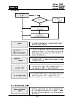
Page 41: ... to look for other menus of setup menu F4 VERSION SRAM TEST OUTPUT TEST LCD TEST DISPLAY CURRENT F W VERSION KEYPAD TEST key 4 or 6 key 4 or 6 key 4 or 6 key 4 or 6 SEARCHING KEY 4 or 6 SRAM TEST OUTPUT TEST LCD TEST KEYPAD TEST READER TEST READER TEST INPUT TEST INPUT TEST COMM TEST COMMUNICATION TEST RS 232 key 4 or 6 key 4 or 6 key 4 or 6 ...

Page 42: ...ceed on and off twice for each output The first two tests are for the output relays Relay 1 Relay 2 You can hear the mechanical sound of relays and following two tests are for TTL output testing The last test is for the built in buzzer and you can hear two beep sounds Press any key to return to the setup menu OUTPUT TEST Relay 1 test Activated two times ENT Relay 2 test Activated two times TTL Out...

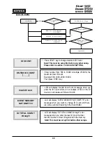
Page 43: ...sappear from the LCD Note that F1 key is A F2 key is B F3 key is C F4 key is D ESC key is E and ENT key is F on the screen After the test is done it returns to setup menu Press ENT key for the reader test LCD will display Scanning for reading the cards Present the card to one of the readers When the reader successfully reads the card LCD will display reader number and the 8 digit card number on th...

Page 44: ...RS232 RX and RS232 TX wires together Then press ENT key This test is a loop test and 505R sends a character to RS232 TX and check whether the RS232 RX receive the character or not If you have an error please contact our service facility After the test is done LCD will display COMM test pass Press any key to return to the setup menu ...

Page 45: ... is to be applied Index No Relay 1 Relay 2 TTL1 TTL2 BUZZER 1 Exit Button 03 00 00 00 00 2 Door Contact 00 03 03 03 03 3 AUX 1 00 00 00 00 00 4 AUX 2 00 00 00 00 00 5 Tamper S W 00 99 99 99 99 6 Reader1 ID OK 03 00 00 00 00 7 Reader1 ID Error 00 03 00 00 00 8 Reader1 ID T S Error 00 03 00 00 00 9 Reader1 APB Error 00 03 00 00 00 10 Reader2 ID OK 03 00 00 00 00 11 Reader2 ID Error 00 03 00 00 00 12...

Page 46: ...f Solution 1 Check if the Back Up Battery Jumper has been shortened 2 Check if the voltage of Back Up Battery is over 3 6V 3 If it is over 3 6V make initialization process as below Connect the cyan wire pink wire and black wire together Main power ON Enter key 1 Check if the LCD shows message of Initialize END turn off Power Main power OFF Separate 3 wire pink cyan and black GND Main power ON agai...

Page 47: ... the LCD and turn it off and on again Try entering the Setup mode Note that all the value will be set to default including the IDs after initializing 3 If the trouble remains after the procedure above contact a service center No problem with accessing by card but cannot access with the PIN input Cause An error in Setup or possible component defect Solution 1 Check whether a beep sound is generated...

Page 48: ...ins after checking the above contact a designated service center ACCESS DOOR ERR message shows when the RF ID card is read Cause Incorrect user setting or false of internal circuit Solution 1 If the unit used to operate properly maybe there has been an electric shock that damaged the internal memory and data Please initialize the unit as instructed in the manual 2 Check if ID information has been ...

Page 49: ...heck if the controller s COMM ID is listed on the application S W Set the different COMM ID when two or more controllers are installed Check if the baud rate 9600bps default is the same as the setting on the S W Make sure that the PC s COM port is set correctly on the S W The parameters at the S W should be set as following Parity bit NONE Data bit 8 bits Stop bit 1 bit 2 Check the line connection...

Page 50: ...rsuant to Part 15 of the FCC Rules These limits are designed to this equipment generates uses and can radiate radio frequency energy and if not installed and used in accordance with the instructions may cause harmful interference to radio communications However there is no guarantee that interference will not occur in a particular installation If this equipment does cause harmful interference to r...

Page 51: ...resent what property is located where this product will be used it would be extremely difficult to determine the actual damages that may result from a failure of the product to perform as anticipated and the low price of this product is based upon the nature of the product provided and the limited liability that IDTECK assumes IDTECK IS NOT RESPONSIBLE FOR ANY PERSONAL INJURY PROPERTY DAMAGE OR LO...

Page 52: ...n RMA Code 1 Company Name 2 Model Name 3 Serial No 4 Original Invoice No 5 Distributor 6 Purchasing Date 7 RMA Request Date Please check your problems Card Reading Power Keypad Communication Relay LCD LED Buzzer Registration Others IDTECK RMA Center 3F 10 10 1 10 2 Dodang Dong Weonmi Gu Bucheon Si Gyeonggi Do 157 030 Korea Telephone 82 2 2659 0055 HQ 82 32 671 5642 RMA Center Fax 82 2 2659 0086 HQ...

Page 53: ...53 16 Template ...

Page 54: ...505RHE5X The specifications contained in this manual are subject to change without notice at any time 5F Ace Techno Tower B D 684 1 Deungchon Dong Gangseo Gu Seoul 157 030 Korea Tel 82 2 2659 0055 Fax 82 2 2659 0086 E mail webmaster idteck com ...

Reviews: