background image


Quick Installation Guide 

3. INSTALLATION TIPS & CHECK POINT 

3.1 Check Points before Installation 

3.1.1 Installation Layout 


Figure: System Installation Layout 

3.1.2 Recommended Cable Type   

*

 Thicker wires are needed if you connect a reader with high current consumption

Reference 

Description 

Cable Specification 


505R/Finger007 series Power (DC12V) 
DC Power 

->

 505R/Finger007 series 

Belden #9409, 18 AWG 

2 conductor, unshielded 


Reader (Power and Data) 

External Reader 

-> 

505R/Finger007 series 

Belden #9512, 22 AWG 

4 conductor, shielded 

Belden #9514, 22 AWG 

8 conductor, shielded 


Door Contact 
Exit Button 

Sensor Input 
Input -> 505R/Finger007 series 

Belden #9512, 22 AWG 

4 conductor, shielded 

Belden #9514, 22 AWG 

8 conductor, shielded 


Door Lock, Alarm Device 

Lock (Alarm) -> 505R/Finger007 series 

Belden #9409, 18AWG 

2 conductor, unshielded 


RS232 Cable 

Converter -> Host P.C 

Belden #9829, 24 AWG 

2 twisted pair, shielded 


505R/Finger007 series -> 505R/Finger007 series 
505R/Finger007 series -> Converter 

Belden #9829, 24 AWG 

2 twisted pair, shielded 

RS422 Cable 
505R/Finger007 series -> 505R/Finger007 series 
505R/Finger007 series -> Converter 

Belden #9830, 24 AWG 

3wisted pair, shielded 

Summary of Contents for Star 505R

Page 1: ...Quick Installation Guide 505R FINGER007 SERIES STANDALONE CONTROLLER...

Page 2: ...Quick Installation Guide 505R Series Standalone Controller 505R IP505R SR505 SR505B FINGER007 IP FINGER007 FINGER007SR FINGER007SRB FINGER007 Series Standalone Controller...

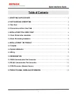
Page 3: ...N TIPS CHECK POINT 4 3 1 Check Points before Installation 4 3 2 Check Point during Installation 5 4 INSTALLATION OF THE PRODUCT 7 4 1 Template 7 4 2 System Initialization 8 4 3 Wiring 9 5 COMMUNICATIO...

Page 4: ...alize Star FINGER007 For initialization press down this switch and then keep it more than 2 seconds 2 Communication Display LED 3 4 orange green LED will twinkle when using RS232 and RS422 communicati...

Page 5: ...r CONTACT Yellow with Red Stripe Aux Input 1 IN1 Green Aux Input 2 IN2 Green with White Stripe EXTERNAL READER PORT CON5 Wiegand Data0 IN DATA0 Pink Wiegand Data1 IN DATA1 Cyan OUTPUT CON5 TTL Wiegand...

Page 6: ...ger007 series Belden 9512 22 AWG 4 conductor shielded Belden 9514 22 AWG 8 conductor shielded Door Contact Exit Button Sensor Input Input 505R Finger007 series Belden 9512 22 AWG 4 conductor shielded...

Page 7: ...stabilizing time 18 6us is much before the center of the Bit therefore the Termination Resistors are not required However if you install the cable to maximum length the impedance of cable and network...

Page 8: ...eld wires in order to prevent noise being created one could interfere the communication from unequal voltage level A proper way to ground is to connect only one end of shield wire of communication cab...

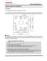
Page 9: ...e center hole Apply force to the main unit firmly to be fixed on the wall Please make sure that the main unit is completely fixed onto the wall mount CAUTION It is recommended to run operational test...

Page 10: ...u see the display shown below Press number 1 key to initialize the device Otherwise press number 0 Figure The Position of Initialization Switch 1 Press the key 1 if you wish to initialize the 505R FIN...

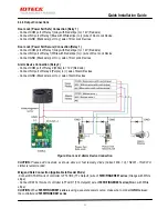
Page 11: ...er wire from the Exit Button to the GND Black wire Door Contact Sensor Connection Contact Connect one wire from Door Contact Sensor to Yellow wire with Red stripe Connect the other wire from Door Cont...

Page 12: ...nd the GND to activate the Cut Off Check function First select whether or not to check the Cut Off status of each device from F2 SETUP MENU 5 IN OUT DEFINE 21 CUT OFF CHECK Second set the desired outp...

Page 13: ...nnection Relay 2 Connect COM port of Relay 2 White to 12V Red wire Connect NO port of Relay 2 Purple to wire of Alarm Devices Connect GND Black wire port to wire of Alarm Devices Figure Door Lock Alar...

Page 14: ...using a separate power source make sure to connect GND between the controller and the external reader Compatible Readers External Reader 505R IP 505R FINGER007 IP FINGER007 Standard 26BIT Wiegand Form...

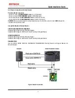
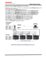
Page 15: ...far A USB to serial converter is recommended if the PC has no COM ports 5 2 RS 422 Communication Port Connection 5 2 1 RS 422 Connection Standalone An RS422 RS232 converter is required to use RS422 co...

Page 16: ...o RS422 RX of another 505R Finger007 series Connect RS422 RX of one 505R Finger007 series to RS422 RX of another 505R Finger007 series Second you have to connect one of RS422 port of 505R Finger007 se...

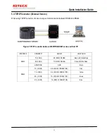
Page 17: ...re TCP IP Converter between 505R FINGER007 series and Host PC INTERFACE FINGER007 ILAN422 LINE COLOR RS232 TX CON2 RX RS232 DSUB9 Black with White Stripe RX CON2 TX RS232 DSUB9 Red with White Stripe G...

Page 18: ...a manual for 4 At the bottom part of the product s page you selected click DOWNLOAD button to download the manual For un registered users of our homepage 1 Visit IDTECK s homepage www idteck com 2 Cl...

Page 19: ...17 Quick Installation Guide MEMO...

Page 20: ...right 2016 IDTECK Co Ltd The specifications contained in this manual are subject to change without notice at any time 5F Ace Techno Tower B D 468 Gangseo Ro Gangseo Gu Seoul 07573 Korea Tel 82 2 2659...

Reviews: