background image

p.10

Summary of Contents for Star IP-RFL200C
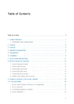
Page 1: ......

Page 2: ... 1 Connecting a power supply 2 Connecting a door lock 3 Connecting an exit button 4 Connecting a door sensor 5 Connecting a door lock type 6 RS485 Communication port connection 9 Network connection to the access controller 10 Set up Hardware 1 Set up System Address and Normal or Toggle Mode 2 Set In Out Point 3 Card Holder Registration or Deletion 4 System Initialization ii 1 3 4 5 6 7 9 11 12 12 ...

Page 3: ...n the RFL200C IP RFL200C while the door is open 5 When you need to know the Board ID or Communication Address 6 To initialize the RFL200C IP RFL200C 7 Besides the operations described above users can register or delete cards using the STAR RFL200C software as well Using this software you can also adjust or change Normal Mod e Toggle Mode Door Open Time and LED Color Control 12 FCC REGISTRATION INF...

Page 4: ...he user to the presence of importa nt operating and maintenance servicing instructions in the literature accompanying the ap pliance WARNING To reduce the risk of fire or electric shock do not expose this appliance to rain or moisture WARNING 1 Be sure to use only the standard adapter that is specified in the specification sheet Usin g any other adapter could cause fire electrical shock or damage ...

Page 5: ...way SAMSUNG is not liable for problems caused by unauthorized modifications or attempted repair 10 When cleaning do not spray water directly onto parts of the product Doing so may ca use fire or electric shock CAUTION 1 Do not drop objects on the product or apply strong blows to it Keep away from a locat ion subject to excessive vibration or magnetic interference 2 Do not install in a location sub...

Page 6: ...fety If the provided plug does not fit into your outlet consult an electrician for repla cement of the obsolete outlet 10 Protect the power cord from being walked on or pinched particularly at plugs convenie nce receptacles and the point where they exit from the apparatus 11 Only use attachments accessories specified by the manufacturer 12 Use only with cart stand tripod bracket or table specified...

Page 7: ...le Door Access Controller which can be mounted to metal door frame mullion or to any flat wall surface The Star RFL200C iPASS IP RFL200C is epoxy potted that ensure you a successful operation even in harsh environments Two color LED of green and red inside Piezo buzzer sound will guarantee you an accurate a nd reliable Door Access Operations ...

Page 8: ... Network Communication via RS485 Max 255ch TCP IP External LAN Converter required optional Wireless e g Bluetooth module required optional 512 Users 256 Event Buffers Direct Control of Door Lock Power Fail Safe or Power Fail Secure Locks Selectable Solid Epoxy Potted Waterproof Warranty Life Time Compatible Software STAR RFL200C ...

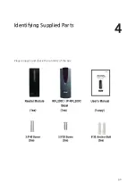
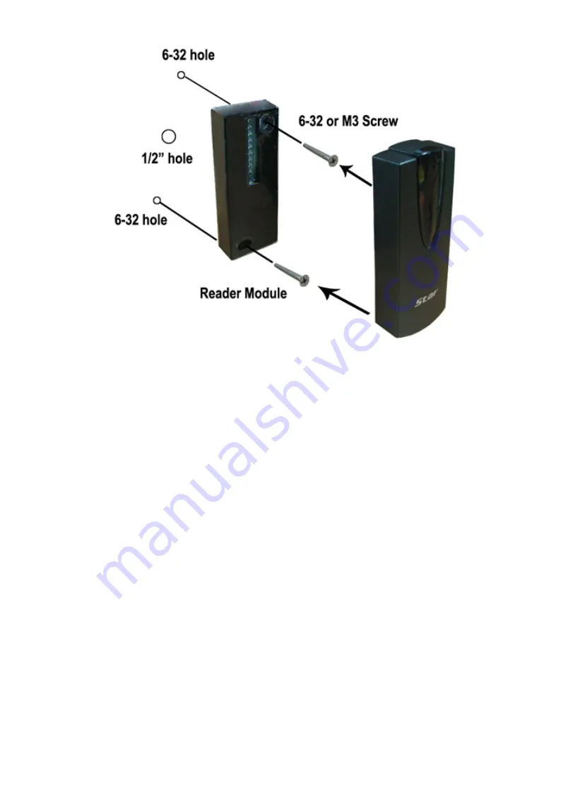
Page 9: ...Identifying Supplied Parts 4 p 6 Please unpack and check the contents of the box ...

Page 10: ... 5 cm IPC80 IPC170 Up to 4 inch 10cm Active Typ e IDA150 IDA200 Compatible N A Time Card 30ms Door Open Time 1 99sec Selectable Power Current DC 12V Max 150mA Communication RS485 Max 255ch Input Port 3ea Exit Button Door Sensor Aux 1 Output Port 2ea TR Output open collector output Rating Max 300mA Alarm Output 1A Lock Output LED Indicator Beeper 9 Array LED Indicators Red and Green Piezo Buzzer Op...

Page 11: ...umidity 10 to 90 relative humidity non condensing Color Dark Pearl Gray Material Polycarbonate Dimension W x H x T 45mm x 124m x 19 64mm 1 8 x 4 9 x 0 8 Weight 80g 0 18 lbs Warranty Life Time Certification FCC CE MIC ...

Page 12: ...odule through the central hole 2 Drill one 0 39 10mm in right horizontal and 1 74 44 4mm in upper vertical through the central hole And drill the other 0 33 8 5mm in left horizontal and 1 59 40 6mm in under vertical through the central hole 3 Push reader module on mullion or wall mount then install the main unit using two 6 32 or M3 screws ...

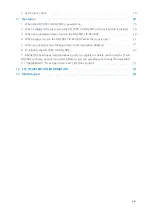
Page 13: ...p 10 ...

Page 14: ...Color Coded Wiring Table 7 p 11 ...

Page 15: ...Wire Connection to Controller 8 p 12 1 Connecting a power supply Connecting a power supply Connect 12V of power supply to Red wire Connect GND of power supply to Black wire ...

Page 16: ...t COM terminal of door sensor to Blue wire of door sensor input Connect NO terminal of door sensor to GND of power supply 5 Connecting a door lock type In a power fail safe connect GND wire of power supply to Yellow wire of door lock type input In a power fail secure put a floating state on Yellow wire of door lock type input 6 RS485 Communication port connection The INC300 for RS485 RS232 convert...

Page 17: ...4 RS485 Communication port connection Plug 9 pin connector of converter into COM Port of the PC Install the application software and then run 485 Converter RFL200C IP RFL200C 485 Orange wire 485 Gray wire ...

Page 18: ... to the access controller 9 p 15 You can install up to 255 Units of RFL200C IP RFL200C as in the below figure Max 255 units Board ID 1 255 can be installed in a loop Able to connect directly via RS485 or RS232 converter ...

Page 19: ... iPASS IP RFL200C are set by the application software 1 Set up System Address and Normal or Toggle Mod e 1 Choose System Name and System Address on drop down list 2 Click Normal Mode or Toggle Mode 3 Click Save and then Transmit button if finishing to step ...

Page 20: ...Safe or Power Fail Secure 3 If clicking Save button one door among System Door Address is checked 4 Click Transmit button 3 Card Holder Registration or Deletion Card Holder Registration or Deletion is performed by the application software 1 Choose INPUT CARD DATA and EMPLOYEE INFORMATION 2 Click Save and then Transmit button ...

Page 21: ...p 18 System Initialization 4 System Initialization StarRFL200C iPASS IP RFL200C is initialized by the software ...

Page 22: ...Set up Hardware p 19 5 LED Color Control The Star RFL200C iPASS IP RFL200C can change its LED color to red or green by the applic ation software ...

Page 23: ...a registered tag is read on the RFL200C IP RFL 200C or the exit button is pressed 1 All LEDs switch from red to green then they turn off sequentially from top to bottom After all LEDs are off they turn on red again 2 The door opens for a predefined length of time and the first two LEDS from the top tur n red indicating the open status of the door 3 The RFL200C IP RFL200C beeps once 3 When an unreg...

Page 24: ...e the authentication status access granted or denied 5 When you need to know the Board ID or Communica tion Address 1 Connect the purple and blue wires together while power is not supplied 2 Apply power and the first LED flashes on and off either red or green and the rest of th e LEDs show the Board ID 3 After checking the Board ID power off the RFL200C IP RFL200C and return the purpl e and blue w...

Page 25: ...n and turn off 3 Then green LEDs are lit sequentially from bottom to top All LEDs turn green 4 The RFL200C IP RFL200C beeps four times indicating the completion of initialization 5 After initialization is finished return the white green and yellow wires to their original positions 6 Power on the RFL200C IP RFL200C again and it will operate normally again 7 Besides the operations described above us...

Page 26: ...e received including interference that may caus e undesired operation This equipment has been tested and found to comply with the limits for a Class A Digital De vice pursuant to Part 15 of the FCC rules These limits are designed to this equipment gener ates uses and can radiate radio frequency energy and if not installed and used in accordan ce with the instructions may cause harmful interference...

Page 27: ...g Gangseo Gu Seoul 157 030 Korea Tel 82 2 2659 0055 Fax 82 2 2659 0086 E mail webmaster idteck com Website www idteck com E Training Center http www idtecktraining com IDTECK Production Facility and RMA Center 2F 89 4Dodang Dong Weonmi Gu Bucheon Si Gyeonggi Do 420 130 Korea Tel 82 2 2659 0055 Fax 82 2 2659 0086 E mail webmaster idteck com Website www idteck com E Training Center http www idtecktr...

Reviews: