ID GATE 6000 Electromechanical Tripod Turnstile
17
8 INSTALLATION INSTRUCTIONS
Follow the safety requirements during the installation (see Clause 7.1)
8.1 Installation details
Correct turnstile installation provides its functionality and lifetime. Please carefully study
and follow the installation instructions.
It is recommended:
•
to mount the turnstile on steady and level concrete (grade 400 or higher), stone or
similar foundations at least 150mm thick;
•
to level the foundation so that the anchoring points of the turnstile lie in the same
plane;
•
to apply reinforcing elements (400×400×300mm) for installation on less steady
foundation (frame foundation, for example).
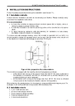
To ensure accurate passage tracking, when the turnstile is operated from an ACS, it is
recommended to create the passage area in such a way that the barrier arms should turn
in the direction of movement at the angle no less than 70° (Fig. 9).
Figure 9. Site preparation. Recommendations
The turnstile is equipped with the resetting device that operates as follows:
o
at the barrier arm turning at the angle of more than 60°±5° the reset is effected in
the direction of movement and the turn of barrier arm to counter direction is not
possible (blocking of return passage) ;
o
at the barrier arm turning at the angle less than 60°±5° the reset is effected
in the counter to the movement direction (reset to home position).
When planning the passage area, it is necessary to arrange additional emergency exit. For
example, it can be the automatic rotary section BH-02 (Clause 9.4).
8.2 Installation tools
•
1.2÷1.5 kW hammer drill;
•
Ø16 mm hard-alloyed drill bits;
•
Floor chaser for electric raceway;
•
Flat slot screwdriver No.2;
•
Cross-head screwdriver;


