Assembly & Operation Manual
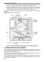
Figure 13. Turnstile cover connection layout
Table 2. Connection layout description
Legend
Name
Q-ty
Note
A1
Control mechanism
1
A2 Turnstile
cover
1
A3, A4
Indication blocks, side (IB1, IB2)
2
A3.1, A4.1
Indication modules (IM1, IM2)
2 For IM1 – jumper in position L,
for IM2 – jumper in position R
A3.2, A4.2
Lighting modules (LM1, LM2)
2
A5
Dynamic indication module
1
A6
Optical arm rotation sensors
1
A7
Electric motors (M1, M2)
1
A8 Electromagnet
1
A9 CLB
1
CLB.140
A10 RC
panel
1
A11
Turnstile power supply
1 12V, 6A
A12
1
WRC
kit
1
A13
1
Access
control
system
1
A14
1
Emergency
unblocking
device
(
Fire Alarm)
1
A15.1
1
, A15.2
1
Remote indicators
2 RI A, RI B
A16
1
Remote indicator power supply
1
A17
1
Siren
1
12VDC
A18
1
Intrusion
detector
1
XS1
Connector block, 24 contacts
1 PSK1/12 (12) Klemmsan ×2
S1
A2 cover connection slot
1
1 Power
cable
1
2 Control
cable
1
3
CLB indication cable
1
4
Turnstile cover indication cable
1
5.1, 5.2
Lighting module cables
2
6.1, 6.2
Dynamic indication module cables
2
7
Wire jumper. Installed when the emergency
unblocking device (A14) is not connected
1 Installed
on
default
8
Wire jumper. Installed when the intrusion
detector (A18) is not connected
1 Installed
on
default
7
Supplied on request.
22

