Assembly & Operation Manual
8
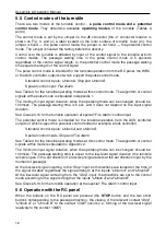
Figure 3. RC panel overall view
1, 2, 3
–
buttons
LEFT
,
RIGHT
,
STOP
for setting the passage mode;
4, 5
–
green indicators
«Left»
,
«Right»
;
6
–
red indicator
«Stop»,
7
–
RC cable.
The RC panel / WRC / ACS controller (13), emergency unblocking device
Fire Alarm
(10),
remote LED indicators, control mechanism and the turnstile power supply unit (9) are
connected to the CLB with the cables in accordance with the connection layout (see
Fig. 12).
The RC panel is designed as a small desktop device with a shockproof ABS plastic case
and is intended for setting and indicating operating modes when the turnstile is operated
manually. The RC panel overall view is shown in Fig. 3.
There are three control buttons on the RC front panel intended for setting the turnstile
operating modes. The LED indicators are located above the buttons. The middle button on
the RC panel (hereinafter
—
the
STOP
button) is intended to set the turnstile to the
“Always lo
c
ked” mode. The left
(
LEFT
) and the right (
RIGHT
) buttons are intended to
unlock the turnstile for passage in the chosen direction.
The RC panel is connected to the CLB with a multicore cable (14) via the
XS1
connector
block (See Fig. 12).
If the turnstile orientation relatively to the
operator’s
terminal is not standard (e.g. the
terminal is placed at the backside of the turnstile housing), the RC panel orientation
towards the turnstile can be changed by exchanging places of the RC wires to the contacts
“Unlock A” and “Unlo
c
k B” as well as con
tacts
“Led A” and “Led B” accordin
gly.


