background image


1.


Product Outline 

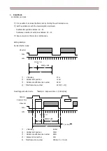
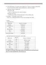
ID1MB-CL/ID1MC-CL is a Camera Link interfaced and 1.2Mega resolution camera module. 
1.2Mega pixels CMOS sensor with diagonal length 6mm is utilized. Entire pixels can be read out 
within 1/54s at CL Base Configuration output. 


Features 


Global Shutter CMOS sensor is utilized. 


Camera Link Base Configuration is supported. 


Fixed trigger shutter mode. 


Binning mode(2x2), VGA mode, QVGA mode. 

 
2.


Handling Precautions 

The camera must not be used for any nuclear equipment or aerospace equipment with which mechanical 

              failure or malfunction could result in serious bodily injury or loss of human life. Our warranty does not apply to 
              dameges or defects caused by irregular and /or abnormal use of the product. 

Please observe all warnings and cautions stated below. 

              Our warranty does not apply to damages or malfunctions caused by neglecting these precautions. 


Do not use or store the camera in the following extreme conditions : 

                  - Extremely dusty or humid places. 
                  - Extremely hot or cold places (operating temperature -5

  to +45

). 

                  - Close to generators of powerful electromagnetic radiation such as radio or TV transmitters. 
                  - Places subject to fluorescent light reflections. 
                  - Places subject to unstable (flickering, etc.) lighting conditions. 
                  - Places subject to strong vibration. 
 
              · Remove dust or dirt on the surface of the lens with a blower. 
              · Do not apply excessive force or static electricity that could damage the camera. 
              · Do not shoot direct images that are extremely bright (e.g., light source, sun, etc.), and when camera is not 
                  in use, put the lens cap on. 

· Confirm the mutual ground potential carefully and then connect the camera to monitors or computers. 

                  AC leaks from the connected devices may cause damages or destroy the camera. 
              · Do not apply excessive voltage. (Use only the specified voltage.)    Unstable or improper power supply 
                  voltage may cause damages or malfunction of the camera. 
              · The voltage ripple of camera power DC +12V

±

10% shall be within 

±

50mV.    Improper power supply 

                  voltage may cause noises on the video signals. 
              · The rising time of camera power supply voltage shall be less than +10V, Max 60ms.    Please avoid   
                  noises like chattering when rising. 

Summary of Contents for ID1MB-CL (B/W)

Page 1: ...1 2Mega CMOS Camera ID1MB CL B W ID1MC CL COLOR Technical Manual iDule Corporation...

Page 2: ...ronous Signals Timing 2Tap Base Configuration 11 5 7 Horizontal Synchronous Signals Timing 2Tap Base Configuration Fixed trigger shutter mode 12 5 8 Vertical Synchronous Signals Timing 2Tap Base Confi...

Page 3: ...Extremely hot or cold places operating temperature 5 to 45 Close to generators of powerful electromagnetic radiation such as radio or TV transmitters Places subject to fluorescent light reflections P...

Page 4: ...0dB 6 Minimum Illumination B W F1 4 4lx Color F1 4 8lx at shutter speed 1 54s OFF Gain 12dB 7 Power Requirements DC 12V 10 12pin PoCL 8 Power Consumption typ 0 9 W max 1 1 W 9 Dimensions H 29 0mm W 29...

Page 5: ...DS Serial to Camera SerTFG Camera Link LVDS Serial to Frame Grabber 6 Video Signals White Clip Level FFEh at Gain 0dB 12bit Setup Level under 0C0h Dark Shading Both horizontal and vertical should be u...

Page 6: ...3 3 Spectral Response Representative Value ID1MB CL B W ID1MC CL Color...

Page 7: ...D light when it is supplied electricity from the frame Grabber board PIN NO PIN NO 1 12V PoCL 14 GND 2 X0 15 X0 3 X1 16 X1 4 X2 17 X2 5 Xclk 18 Xclk 6 X3 19 X3 7 SerTC 20 SerTC 8 SerTFG 21 SerTFG 9 CC...

Page 8: ...4 3 12pin Connector HR10A 10R 12PB 74 HIROSE Do not supply power from both P1 and CN1 PIN NO 1 GND 2 Power Input DC 12V 3 GND 4 NC 5 GND 6 FVAL out 7 Exposure out 8 GND 9 NC 10 NC 11 Trigger in 12 GND...

Page 9: ...Configuration LVAL Out Effective Data 1284 CLK 104 CLK DVAL Out 1H 1388 CLK Camera Link CLK 74 25MHz Camera Link Port A 1 2 3 4 1 2 8 1 1 2 8 2 1 2 8 3 1 2 8 4 1 Video Out 2 1 2 8 3 1 2 8 4 3 4 1 2 8...

Page 10: ...LVAL Out Effective Data 1284 CLK 366 CLK DVAL Out 1H 1650 CLK Camera Link CLK 74 25MHz Camera Link Port A 1 2 3 4 1 2 8 1 1 2 8 2 1 2 8 3 1 2 8 4 1 Video Out 2 1 2 8 3 1 2 8 4 3 4 1 2 8 1 1 2 8 2 FVAL...

Page 11: ...ion LVAL Out Effective Data 642 CLK 52 CLK DVAL Out 1H 694 CLK Camera Link CLK 37 125MHz Camera Link Port A 1 3 1281 1283 1 Video Out 2 1 2 8 3 1 2 8 4 3 4 1 2 8 1 1 2 8 2 Camera Link Port B 2 4 1282...

Page 12: ...L Out Effective Data 642 CLK 183 CLK DVAL Out 1H 825 CLK Camera Link CLK 37 125MHz 1 Video Out 2 1 2 8 3 1 2 8 4 3 4 1 2 8 1 1 2 8 2 Camera Link Port A 1 3 1281 1283 Camera Link Port B 2 4 1282 1284 F...

Page 13: ...CLK DVAL Out 1H 1388 CLK Camera Link CLK 74 25MHz R 1 Video Out G 1 G 1 2 8 4 B 1 2 8 4 B 1 R 2 B 1 2 8 3 R 1 2 8 4 Camera Link Port A R1 R2 R1283 R1284 Camera Link Port B G1 G2 G1283 G1284 Camera Li...

Page 14: ...VAL Out 1H 1650 CLK Camera Link CLK 74 25MHz R 1 Video Out G 1 G 1 2 8 4 B 1 2 8 4 B 1 R 2 B 1 2 8 3 R 1 2 8 4 Camera Link Port A R1 R2 R1283 R1284 Camera Link Port B G1 G2 G1283 G1284 Camera Link Por...

Page 15: ...bit RGB Only ID1MC CL 962 Line 1284pixel G2 B1 G 1283 R 1284 G 1284 B 1283 G 1284 D 1283 D 1284 D2 962 Line 1284pixel D1 962 Line 1284pixel G2 B1 G 1283 R 1284 G 1284 B 1283 D 1283 D 1284 D2 962 Line...

Page 16: ...the exposure period and before the image output is completed Possible trigger input interval Exposure Time Delay Exposure Time Effective Line 18 5H 27H Example Exposure time 1 1000s 45H effective lin...

Page 17: ...t work in VGA mode or QVGA mode Setting Example Normal shutter mode V blanking 27H Vertical start position 120H Partial scan effective line number 480H Total frame line number 507H Fixed trigger shutt...

Page 18: ...22us Fixed trigger shutter mode Example Normal shutter mode Effective lines Frame rate Total lines 4H min 1725 6fps 31H 240H QVGA mode 200 3 267 320H 154 1 347 480H VGA mode 105 5 507 640H 80 201 667...

Page 19: ...1 pixel and output The number of pixels is 640 x 480 and the amount of transferred data can be reduced without changing the angle of view The frame rate is the same as the output of all pixels Set to...

Page 20: ...e start position to 2 x n However Satisfy the horizontal start position 640 1284 Satisfy the vertical start position 480 962 The initial data of the horizontal start position is 0000 h and the center...

Page 21: ...osition to 2 x n However Satisfy the horizontal start position 320 1284 Satisfy the vertical start position 240 962 The initial value of the data for the horizontal start position is 0000 h and the ce...

Page 22: ...t Normally a camera returns a control code which is ACK or NAK If return value has a text message the message is between STX and ETX ACK 06H Succeed NAK 15H Fail STX 02H command 2byte parameter ASCII...

Page 23: ...d ETX Address Number of data acquisition optional Return value Succeed STX A R d d ETX Data Data length depends on the number of acquisitions Fail NAK Remarks The command gets some value of register...

Page 24: ...Return Value Succeed ACK Fail NAK Remarks The commands sets free data on the specified register and can use 4 tables 1 table 16 characters 4 Get User s data Command Get User s data STX G U 0 ETX Tabl...

Page 25: ...figuration Restore STX C R ETX Return Value Succeed ACK Fail NAK 7 Get a model name Command Query Model name STX Q M ETX Return Value Succeed STX R M d d ETX Model name Fixed length 16byte Fail NAK 8...

Page 26: ...s undefined 01 The command length is more than defined 02 The address is undefined 03 The value of data is undefined 04 The length is more than defined 05 The table number is undefined 06 The string o...

Page 27: ...ng with a trigger shutter mode because the command received a 01 from the camera 2 How to check trigger shutter mode The command gets consecutive 2 bytes values from address 20 Send Command STX G R 2...

Page 28: ...turn Value The command finished normally because the command received ACK from the camera 4 How to set 01FF for manual shutter The command set 01FF for address 24 Send Command STX S R 2 4 F F 0 1 ETX...

Page 29: ...Return Value The command finished normally because the command received ACK from the camera 6 How to restore the camera to initial settings The command send CR Send Command STX C R ETX Return value f...

Page 30: ...ormally because the command received NAK from the camera When the command did not finish normally retry to send command or send to get detail of a detail error command Send Command STX Q E ETX Return...

Page 31: ...utter mode 00 1 54s OFF 1 45s OFF 01 1 75s 1 75s 02 1 100s 1 100s 03 1 150s 1 150s 04 1 350s 1 350s 05 1 500s 1 500s 06 1 1000s 1 1000s 07 1 2500s 1 2500s 08 1 5000s 1 5000s 09 1 7500s 1 7500s 0A 1 10...

Page 32: ...3 2dB 04 0dB 05 2dB 06 4dB 07 6dB Trigger shutter mode 04 00 Normal shutter mode Trigger OFF 01 Fixed trigger shutter mode Address 01 setting the shutter speed If the gain mode shutter mode and white...

Page 33: ...ed trigger shutter mode 22 222us 02 2 line step Time for line Normal shutter mode 37 387us Fixed trigger shutter mode 44 444us 03 4 line step Time for line Normal shutter mode 74 774us Fixed trigger s...

Page 34: ...ure time is the same as the max value 984 Line step slow shutter 26 27 LLHH min 0 0H max 64550 FC26H Shutter time 985 setting value time for line 1 frame time is 989 set value x line time See address...

Page 35: ...0 3C0H Setting value 2 x n Partial scan Effective line number 50 51 LLHH min 2 2H max 962 3C2H When not in use set the number of valid lines 962 3C2H To enable partial scan change the data at address...

Page 36: ...8 Dimensions mm...

Page 37: ...n 0B 00 8bit Baud Rate 10 00 9600bps Slow shutter mode 13 00 OFF Output Image Flip 18 00 Normal LED ON OFF 1B 01 ON Manual Gain 20 21 0000 0dB Manual Shutter 24 25 0000 Shutter OFF Line step slow shut...

Page 38: ...in this product specification operation manual In case damage or losses are caused by malfunction or other problems resulting from use of equipment or software that is not specified In case damage or...

Reviews: