Industrial Electronic Engineers, Inc.
SIZE
A
CODE IDENT NO.
05464
S036X2–XXX–XXXXX
Van Nuys, California
SCALE N/A
REV
N
SHEET 21 of 49
04/10/02
3.3
Performance Characteristics
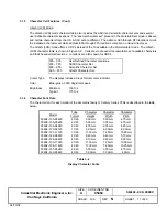
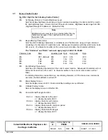
Processor Power–up Cycle
500 msec minimum
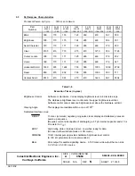
Part
Number
4 X 20
036X2
–100
2 X 20
036X2
–105
2 X 40
036X2
–106
1X20
036X2
-120, -121
2 X 20
036X2
–122, -130
4 X 20
036X2
–124, -134
2 X 40
036X2
–151
4X40
03602
-160
Blink
300
170
176
123
290
470
181
350
Brightness
305
170
175
124
285
465
184
351
Send Character
315
170
171
126
285
460
179
350
Clear
2105
410
715
215
410
1210
746
1726
Cursor Locate
305
170
171
125
285
460
178
352
Home
300
170
171
123
285
460
176
347
Horizontal Scroll
1830
635
1224
755
585
1055
1260
2738
Reset
850
815
802
765
805
1000
780
711
Vertical Scroll
2510
410
901
270
410
1445
901
3504
Table 3–5
Execution Times (in
µ
µ
sec)
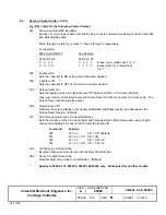
Brightness Control
Software or Hardware. Varies display brightness level in 8 discrete steps.
The Hardware brightness level control sets the upper brightness level limit.
Software control cannot advance brightness level above the hardware set limit.
Viewing Angle
The displays are readable within a cone of 150o.
Dedicated Interface Lines:
RES ET
15 msec (minimum) negative going pulse clears display and initializes processor
power–up sequence.
(Requires current sink capable of discharging a 4.7
µ
F internal capacitor and a 10 k
Ω
resistor to V
CC
.)
BUSY
High during write or hardware reset. Low when ready for data.
(Not used with serial data mode or LCD mode.)
DIMMING
10 k
Ω
internal pull–up provides hardware brightness level control.
(A 100 k
Ω
potentiometer is recommended.)
BELL
Drive output for audible signalling device. A 160 msec wide output that can sink
0.2 A from a 5.0 Vdc source.

