Industrial Electronic Engineers, Inc.
SIZE
A
CODE IDENT NO.
05464
S03858–21–0205
Van Nuys, California
SCALE N/A
REV B
SHEET 10
3.0
THEORY OF OPERAT ION
The serial input option was designed to allow users to send data and control codes to the display module via
the industry standard RS–232C serial interface. This follows the interface protocol of the parallel input Daystar
Nova display modules with few exceptions.
3.1
Serial Interface
The serial input module is a receive only device. Consequently, it is impossible for the host to read data or
status from the LCD controller. This precludes reading of data from the Data Display (DD) RAM, Character
Generator (CG) RAM, or address counter (AC). It is not necessary to read the controller busy flag because a
large serial data input buffer prevents overflow at 9600 baud.
The serial interface requires one start bit, and may be jumper selected to operate with (1) either 7 or 8 data bits
per character and (2) either odd or even parity with one stop bit, or no parity and two stop bits.
Since two command characters and numerous data characters are 8 bits in length, it is recommended to
operate in 8 bit mode if the host has this capability. Where this is not possible, 7 bit mode should be jumper
selected (see section 4.2) and a special command character (19h) must be sent prior to each 8 bit command
or data character; i.e., characters where B
7
= 1.
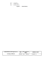
Figure 5 represents serial data formatted as one start bit, eight data bits, an odd or even parity with one stop bit,
or 2 stop bits if no parity.
Mark
Space
B
B
B
B
B
B
B
P
S
B
2
1
0
3
4
5
6
7
(LSB)
(MSB)
Start Bit
8 Data Bits
Figure 5
8–bit Serial Data Format
A logic "1" represents a "mark" condition and a logic "0" represents a "space" condition. For RS–232C the
"mark" and "space" conditions are defined as –3.0 to –25.0 Volts and +3.0 to +25.0 Volts, respectively.
3.2
Error Detection and Reporting
During normal operation, the module will detect and display all parity and framing errors (see Section 3.8).
Each character received in error is replaced with one of the following symbols:
Parity Error
"&"
Framing Error "@"
If the display shows an "@" after power–up, the polarity of the serial interface may be reversed and should be
checked.


