Industrial Electronic Engineers, Inc.
SIZE
A
CODE IDENT NO.
05464
S03858–21–0205
Van Nuys, California
SCALE N/A
REV B
SHEET 23
8.0
EL BACKLIGHTING
8.1
EL Backlight Description
The module contains an AC EL backlight which enables the LCD to read under low lighting conditions. The EL
lamp provides uniform lighting across the entire display surface. Since the lamp is a cold light source, no heat
is added to the module during operation.
8.2
Electrical Characteristics of EL Backlight
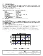
Typical measurements at 115VAC, 400Hz, unless otherwise noted.
Color:
Aviation Green
Radiance:
.051 Watts/ft
2
Spectral peak emission:
520mm
Chromaticity:
X = .230
±
.030, Y = .500
±
.030
Voltage Range:
41 to 130 Volts
Operating Frequency (max.):
600Hz
Power Requirements:
.035 Watts/inch
2
8.3
Operation
8.3.1
Normal Operation
The EL lamp is designed for typical operation at 90 Volts AC at 330 cycles. The light output of the lamp under
these operating conditions is typically 12 ft–L. Since the LCD transmits approximately 8% of the light, the light
output through the display is 1 ft–L.
8.3.2
Brightness and Voltage and Frequency Characteristics
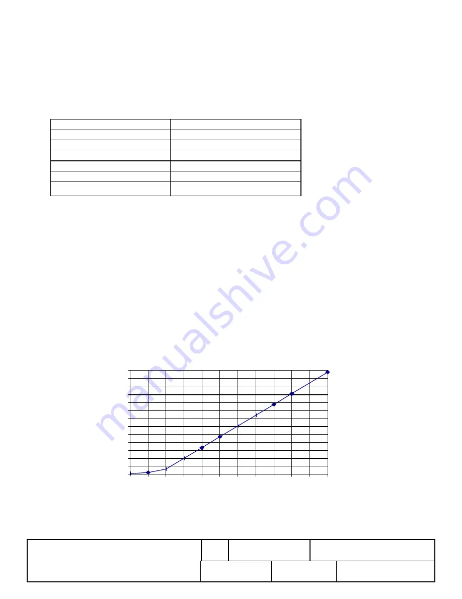
Other voltages and frequencies can be applied to the lamp to increase or decrease the light output. Figure 17
illustrates the relationship between brightness and voltage. Figure 18 illustrates the relationship between
brightness and frequency. A rough approximation of the initial brightness of an aviation green
electroluminescent panel when driven by a sinusoidal waveform can be derived by the following equation.
B = 0.27 x V + 0.0455 x f – 27.7 where: B = brightness of lamp in ft–L, V = voltage applied to lamp in RMS
Volts and f = frequency in Hertz
25ºC, 400Hz, Aviation Green
0
2
4
6
8
10
12
14
16
18
20
22
24
26
20
30
40
50
60
70
80
90
100
110
120
130
Voltage (RMS)
Brightness (foot–Lamberts)
Figure 17
Initial Brightness vs. Voltage


