WAFER-JL-N5105 SBC
Page 53
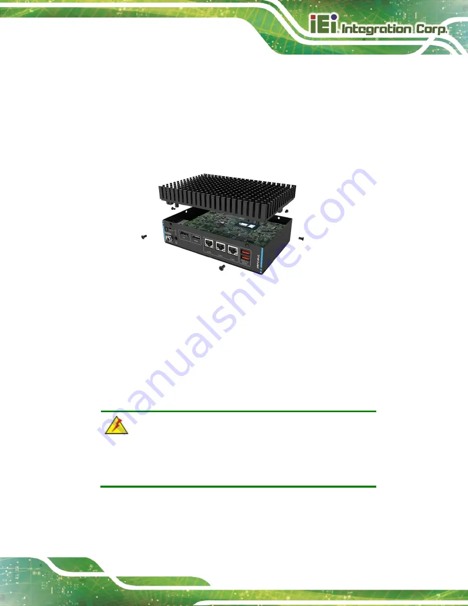
The WAFER-JL-N5105 is also well designed to fit into other chassis in the market. Each
side of the heat spreader has several screw holes allowing the WAFER-JL-N5105 to be
mounted into a chassis or a heat sink enclosure (please refer to Figure 1-3 for the detailed
dimensions). The user has to design or select a chassis or a heat sink enclosure that has
screw holes matching up with the holes on the heat spreader for installing the WAFER-JL-
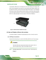
N5105. The following diagram shows an example of motherboard installation.
Figure 4-9: Motherboard Installation Example
4.6
Internal Peripheral Device Connections
This section outlines the installation of peripheral devices to the on-board connectors
4.6.1
AT Power Connection
Follow the instructions below to connect the WAFER-JL-N5105 to an AT power supply.
WARNING:
Disconnect the power supply power cord from its AC power source to
prevent a sudden power surge to the WAFER-JL-N5105.
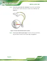
Step 1:
Locate the power cable
. The power cable is shown in the packing list in
Chapter 2
.
Summary of Contents for 167320
Page 12: ......
Page 13: ...WAFER JL N5105 SBC Page 1 Chapter 1 1 Introduction...
Page 20: ...WAFER JL N5105 SBC Page 8 Chapter 2 2 Unpacking...
Page 24: ...WAFER JL N5105 SBC Page 12 Chapter 3 3 Connectors...
Page 58: ...WAFER JL N5105 SBC Page 46 Chapter 4 4 Installation...
Page 71: ...WAFER JL N5105 SBC Page 59 Chapter 5 5 Software Drivers...
Page 74: ...WAFER JL N5105 SBC Page 62 Appendix A A Regulatory Compliance...
Page 76: ...WAFER JL N5105 SBC Page 64 B C Product Disposal Appendix B...
Page 78: ...WAFER JL N5105 SBC Page 66 Appendix C D Error Beep Code...

