ACT-408A-N270 User Manual
Page 17
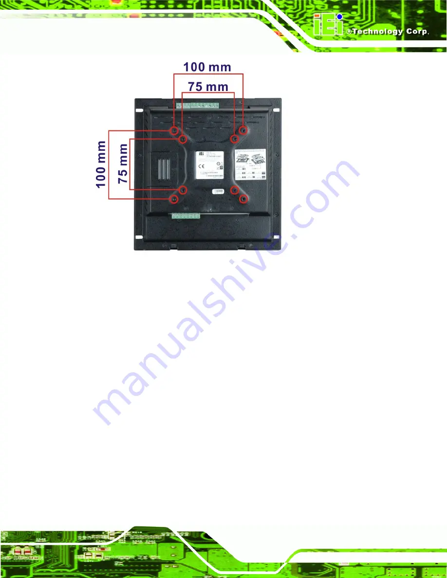
Figure 1-4: ACT-408A-N270 Rear View
1.2.4 I/O Interface Panels
The I/O interface panels located on the bottom and top panels of the ACT-408A-N270
(
Figure 1-5
)
have the following I/O interface connectors:
1 x 12 V DC power jack
1 x RJ-45 RS-232 port
1 x RJ-45 RS-232 or RS-422/485 port
1 x RJ-45 GbE LAN connectors
2 x USB 2.0 ports
1 x 8-pin Wiegand RFID reader input
1 x 8-pin Digital output for door control
1 x 4-pin Digital input
The external I/O interface connectors on the bottom panel are shown in
Figure 1-5
.
Summary of Contents for ACT-408A-N270
Page 12: ...ACT 408A N270 User Manual Page 12 Chapter 1 1 Introduction...
Page 22: ...ACT 408A N270 User Manual Page 22 Figure 1 8 ACT 408A N270 Dimensions mm...
Page 23: ...ACT 408A N270 User Manual Page 23 Chapter 2 2 Installation...
Page 49: ...ACT 408A N270 User Manual Page 49 Chapter 3 3 RFID Reader...
Page 64: ...ACT 408A N270 User Manual Page 64 Chapter 4 4 System Maintenance...
Page 72: ...ACT 408A N270 User Manual Page 72 Chapter 5 5 BIOS...
Page 115: ...ACT 408A N270 User Manual Page 115 Appendix A A External Connector Pinouts...
Page 120: ...ACT 408A N270 User Manual Page 120 Appendix B B Safety Precautions...
Page 124: ...ACT 408A N270 User Manual Page 124 Appendix C C BIOS Configuration Options...
Page 128: ...ACT 408A N270 User Manual Page 128 Appendix D D Watchdog Timer...
Page 131: ...ACT 408A N270 User Manual Page 131 Appendix E E Hazardous Materials Disclosure...