


ACT-408A-N270 User Manual
Page 54
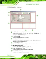
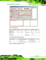
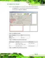
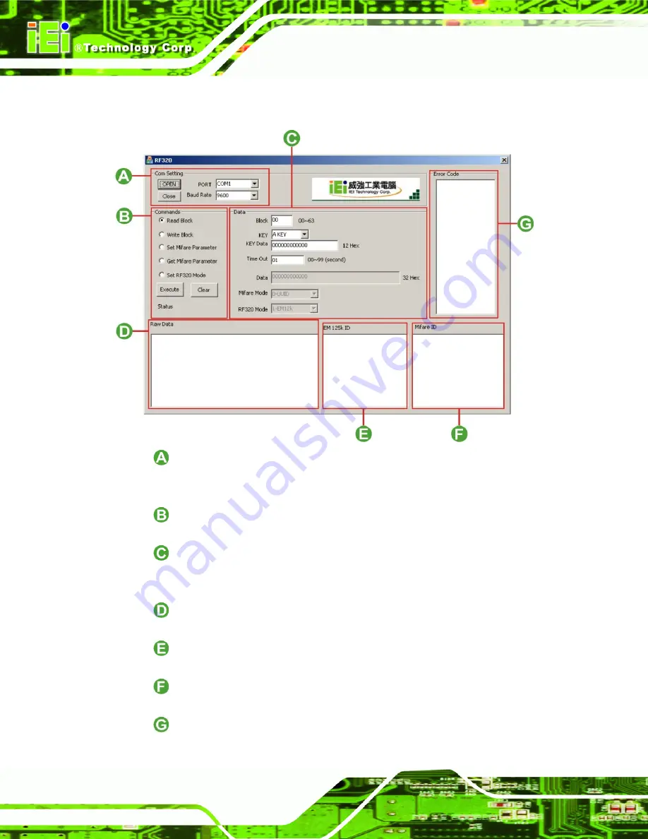
3.3 RF320 Interface Overview
- COM Port Settings and Activation Area
Allows the user to select the serial port used by the ACT-408A-N270 to
communicate with the RFID reader module.
- Commands Area
Shows various request options for user to select.
- Data Input Area
The data input area is where the user enters block number, key, key data, and other
information required by certain commands.
- Raw Data Display Area
Shows all communication logs and responses of the executed commands.
- EM Card ID Display Area
Displays the EM card ID when the EM card is detected.
- Mifare Card ID Display Area
Displays the Mifare card ID when the Mifare card is detected.
Error Code Display Area
Shows the error message when an error occurs.
Summary of Contents for ACT-408A-N270
Page 12: ...ACT 408A N270 User Manual Page 12 Chapter 1 1 Introduction...
Page 22: ...ACT 408A N270 User Manual Page 22 Figure 1 8 ACT 408A N270 Dimensions mm...
Page 23: ...ACT 408A N270 User Manual Page 23 Chapter 2 2 Installation...
Page 49: ...ACT 408A N270 User Manual Page 49 Chapter 3 3 RFID Reader...
Page 64: ...ACT 408A N270 User Manual Page 64 Chapter 4 4 System Maintenance...
Page 72: ...ACT 408A N270 User Manual Page 72 Chapter 5 5 BIOS...
Page 115: ...ACT 408A N270 User Manual Page 115 Appendix A A External Connector Pinouts...
Page 120: ...ACT 408A N270 User Manual Page 120 Appendix B B Safety Precautions...
Page 124: ...ACT 408A N270 User Manual Page 124 Appendix C C BIOS Configuration Options...
Page 128: ...ACT 408A N270 User Manual Page 128 Appendix D D Watchdog Timer...
Page 131: ...ACT 408A N270 User Manual Page 131 Appendix E E Hazardous Materials Disclosure...


