ACT-408A-N270 User Manual
Page 69
Step 9:
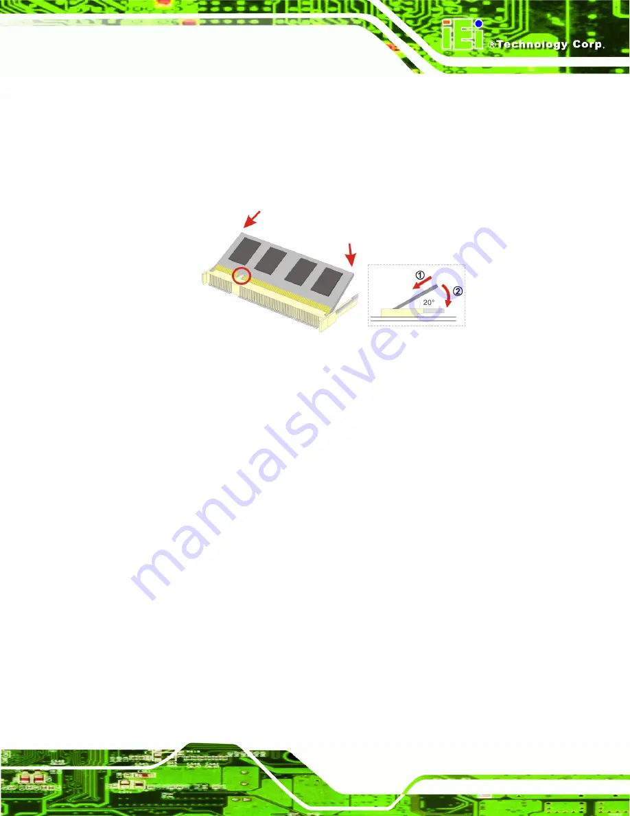
Align the SO-DIMM with the socket
. The SO-DIMM must be oriented in such a
way that the notch in the middle of the SO-DIMM must be aligned with the
plastic bridge in the socket.
Step 10:
Insert the SO-DIMM
. Push the SO-DIMM chip into the socket at an angle
(
Figure 4-3
).
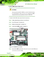
Figure 4-3: SO-DIMM Installation
Step 11:
Secure the SO-DIMM
. Push the SO-DIMM down. The clip into place and secure
the SO-DIMM in the socket.
Step 0:
4.5.3 Wireless Module Replacement
To replace the wireless module, please follow the steps below.
Step 1:
Follow all anti-static procedures
. See
Section 4.2
.
Step 2:
Turn off the power
. See
Section 4.3
.
Step 3:
Remove the back panel
. See
Section 4.4
.
Step 4:
Locate the wireless module
. The wireless module is located below the CPU
heat sink. See
Figure 4-4
.
Summary of Contents for ACT-408A-N270
Page 12: ...ACT 408A N270 User Manual Page 12 Chapter 1 1 Introduction...
Page 22: ...ACT 408A N270 User Manual Page 22 Figure 1 8 ACT 408A N270 Dimensions mm...
Page 23: ...ACT 408A N270 User Manual Page 23 Chapter 2 2 Installation...
Page 49: ...ACT 408A N270 User Manual Page 49 Chapter 3 3 RFID Reader...
Page 64: ...ACT 408A N270 User Manual Page 64 Chapter 4 4 System Maintenance...
Page 72: ...ACT 408A N270 User Manual Page 72 Chapter 5 5 BIOS...
Page 115: ...ACT 408A N270 User Manual Page 115 Appendix A A External Connector Pinouts...
Page 120: ...ACT 408A N270 User Manual Page 120 Appendix B B Safety Precautions...
Page 124: ...ACT 408A N270 User Manual Page 124 Appendix C C BIOS Configuration Options...
Page 128: ...ACT 408A N270 User Manual Page 128 Appendix D D Watchdog Timer...
Page 131: ...ACT 408A N270 User Manual Page 131 Appendix E E Hazardous Materials Disclosure...

