ACT-408A-N270 User Manual
Page 70
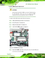
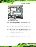
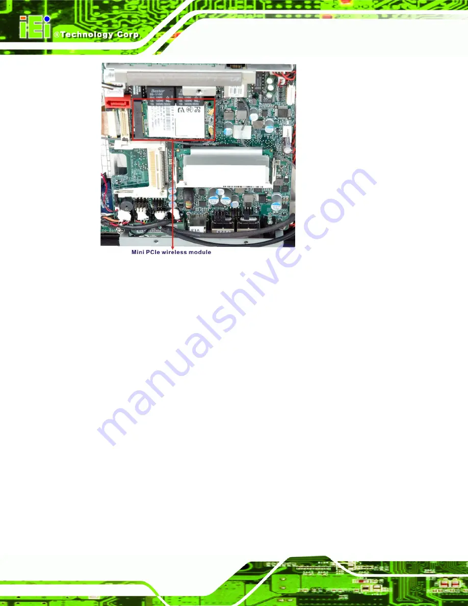
Figure 4-4: Wireless Module Location
Step 5:
Open the Mini PCIe card socket clips
. The Mini PCIe card socket has two
clips that secure the Mini PCIe wireless module into the socket. Before the
wireless module can be removed from the socket, the clips must be opened.
Step 6:
Remove the wireless module
. Once the two clips of the Mini PCIe card socket
are open, remove the wireless module from the socket.
Step 7:
Align the new wireless module with the Mini PCIe card socket
. The wireless
module must be oriented in such a way that the notch in the wireless module
must be aligned with the plastic bridge in the socket.
Step 8:
Insert the wireless module
. Push the wireless module into the socket at an
angle.
Step 9:
Secure the wireless module
. Push the wireless module down until the two
clips into place, securing the card in place.
Summary of Contents for ACT-408A-N270
Page 12: ...ACT 408A N270 User Manual Page 12 Chapter 1 1 Introduction...
Page 22: ...ACT 408A N270 User Manual Page 22 Figure 1 8 ACT 408A N270 Dimensions mm...
Page 23: ...ACT 408A N270 User Manual Page 23 Chapter 2 2 Installation...
Page 49: ...ACT 408A N270 User Manual Page 49 Chapter 3 3 RFID Reader...
Page 64: ...ACT 408A N270 User Manual Page 64 Chapter 4 4 System Maintenance...
Page 72: ...ACT 408A N270 User Manual Page 72 Chapter 5 5 BIOS...
Page 115: ...ACT 408A N270 User Manual Page 115 Appendix A A External Connector Pinouts...
Page 120: ...ACT 408A N270 User Manual Page 120 Appendix B B Safety Precautions...
Page 124: ...ACT 408A N270 User Manual Page 124 Appendix C C BIOS Configuration Options...
Page 128: ...ACT 408A N270 User Manual Page 128 Appendix D D Watchdog Timer...
Page 131: ...ACT 408A N270 User Manual Page 131 Appendix E E Hazardous Materials Disclosure...

