ACT-457A Panel PC
Page 15
2.3 Installation and Configuration Steps
The following installation steps must be followed.
Step 1:
Unpack the ACT-457A
Step 2:
Install SD card (if not pre-installed)
Step 3:
Configure the system
Step 4:
Connect peripheral devices to the bottom panel of the ACT-457A.
Step 5:
Mount the ACT-457A
S
te
p
0
:
2.4 Rear Panel Removal
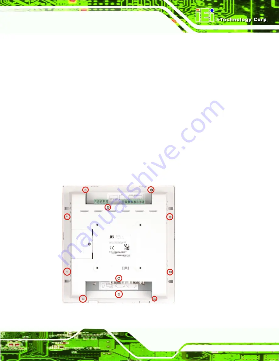
To access the jumpers and connectors, the rear panel must be removed.
Step 1:
Place the ACT-457A monitor side down on a flat surface.
Step 2:
Remove the rear panel screws and lift the back cover off.
S
te
p
0
:
Figure 2-1: Rear Panel Retention Screws
Summary of Contents for ACT-457A
Page 9: ...ACT 457A Panel PC Page 1 Chapter 1 1 Introduction...
Page 18: ...ACT 457A Panel PC Page 10 Figure 1 9 Front Dimensions...
Page 19: ...ACT 457A Panel PC Page 11 Figure 1 10 Cutout Dimensions...
Page 20: ...ACT 457A Panel PC Page 12 Chapter 2 2 Installation...
Page 37: ...ACT 457A Panel PC Page 29 Figure 2 17 Digital I O Cable Installation...
Page 38: ...ACT 457A Panel PC Page 30 Chapter 3 3 RFID Reader...
Page 49: ...ACT 457A Panel PC Page 41 Chapter 4 4 System Maintenance...
Page 53: ...ACT 457A Panel PC Page 45 Appendix A A External Connector Pinouts...
Page 57: ...ACT 457A Panel PC Page 49 Appendix B B Terminology...
Page 61: ...ACT 457A Panel PC Page 53 Appendix C C Watchdog Timer...
Page 64: ...ACT 457A Panel PC Page 56 Appendix D D Hazardous Materials Disclosure...


