ACT-457A Panel PC
Page 24
NOTE:
When purchasing the arm please ensure it has a 75 mm x 75 mm
mounting hole pattern. Only this mounting size will support the
ACT-457A.
Step 2:
Once the mounting arm has been firmly attached to the surface, lift the flat panel
PC onto the interface pad of the mounting arm.
Step 3:
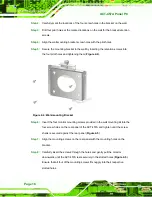
Align the retention screw holes on the mounting arm interface with those in the
flat panel PC. The ACT-457A arm mount retention screw holes are shown in
Figure 2-13: ACT-457A Arm Mounting Retention Screw Holes
Step 4:
Secure the flat panel PC to the interface pad by inserting four retention screws
through the bottom of the mounting arm interface pad and into the flat panel
Summary of Contents for ACT-457A
Page 9: ...ACT 457A Panel PC Page 1 Chapter 1 1 Introduction...
Page 18: ...ACT 457A Panel PC Page 10 Figure 1 9 Front Dimensions...
Page 19: ...ACT 457A Panel PC Page 11 Figure 1 10 Cutout Dimensions...
Page 20: ...ACT 457A Panel PC Page 12 Chapter 2 2 Installation...
Page 37: ...ACT 457A Panel PC Page 29 Figure 2 17 Digital I O Cable Installation...
Page 38: ...ACT 457A Panel PC Page 30 Chapter 3 3 RFID Reader...
Page 49: ...ACT 457A Panel PC Page 41 Chapter 4 4 System Maintenance...
Page 53: ...ACT 457A Panel PC Page 45 Appendix A A External Connector Pinouts...
Page 57: ...ACT 457A Panel PC Page 49 Appendix B B Terminology...
Page 61: ...ACT 457A Panel PC Page 53 Appendix C C Watchdog Timer...
Page 64: ...ACT 457A Panel PC Page 56 Appendix D D Hazardous Materials Disclosure...


