background image


AFOLUX LX Panel PC

Page 36 


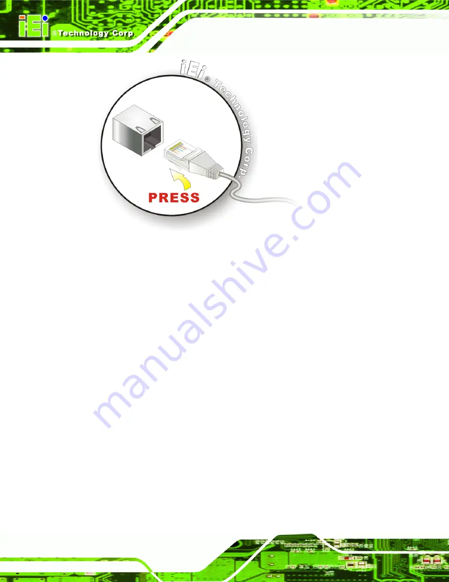
Figure 3-10: LAN Connection 

Step 3: 

Insert the LAN cable RJ-45 connector.

 Once aligned, gently insert the LAN 

cable RJ-45 connector into the onboard RJ-45 connector.


Step 0:


3.8.2 Serial Device Connection 

The AFOLUX LX has two serial device connectors on the bottom panel. The two serial 

device slots (RJ-45) connect to a cable with a standard DB-9 connector at the other end 

(cables included). Follow the steps below to connect a serial device to the AFOLUX LX 

panel PC. 

Step 1: 

Locate the RJ-45 connector

. The location of the RJ-45 serial port connector is 

shown in 

Chapter 2

. The RJ-45 connectors for the serial ports can be identified 

easily as the RJ-45 for the network has two LEDs on the port, while the 

connectors for the serial cables don’t. 

Step 2: 

Insert the RJ-45 to DB-9 cable. 

Step 3: 

Insert the serial connector

.


Insert the DB-9 connector of a serial device into 

the DB-9 connector on the cable. See 

Figure 3-11

Summary of Contents for AFL-056A-LX

Page 1: ...AFOLUX LX Panel PC Page i...

Page 2: ...AFOLUX LX Panel PC Page ii Revision Date Version Changes April 2008 1 00 Initial release...

Page 3: ...arising out of the use or inability to use the product or documentation even if advised of the possibility of such damages This document contains proprietary information protected by copyright All rig...

Page 4: ...Failure to adhere to warning messages may result in permanent damage to the AFOLUX LX or personal injury to the user Please take warning messages seriously CAUTION Cautionary messages should also be h...

Page 5: ...tained therein can help avoid making mistakes Notes are easy to recognize The word note is written as NOTE both capitalized and bold and is followed by text The text is the cautionary message A note m...

Page 6: ...rom or contact an IEI sales representative directly To contact an IEI sales representative please send an email to sales iei com tw The items listed below should all be included in the AFOLUX LX packa...

Page 7: ...IFICATIONS 7 1 4 1 Preinstalled Hardware Components 7 1 4 2 System Specifications 7 1 4 3 Motherboard Specifications 9 1 4 4 Flat Panel Screen Specifications 9 1 4 5 Touch Screen Specifications 10 1 4...

Page 8: ...3 4 1 Packing List 26 3 5 CF CARD INSTALLATION 27 3 6 AT ATX MODE SELECTION 28 3 6 1 AT Power Mode 29 3 6 2 ATX Power Mode 29 3 7 MOUNTING THE SYSTEM 29 3 7 1 Wall Mounting 30 3 7 2 Panel Mounting 32...

Page 9: ...recautions 70 A 1 2 Anti static Precautions 71 A 2 MAINTENANCE AND CLEANING PRECAUTIONS 71 A 2 1 Maintenance and Cleaning 71 A 2 2 Cleaning Tools 72 B BIOS OPTIONS 73 C SOFTWARE DRIVERS 77 C 1 REMOTE...

Page 10: ...ESS MAP 96 G 2 1ST MB MEMORY ADDRESS MAP 97 G 3 IRQ MAPPING TABLE 97 G 4 DMA CHANNEL ASSIGNMENTS 98 H HAZARDOUS MATERIALS DISCLOSURE 99 H 1 HAZARDOUS MATERIALS DISCLOSURE TABLE FOR IPB PRODUCTS CERTIF...

Page 11: ...ng Bracket 30 Figure 3 5 Chassis Support Screws 31 Figure 3 6 Secure the Panel PC 32 Figure 3 7 Panel Opening 33 Figure 3 8 Tighten the Panel Mounting Clamp Screws 34 Figure 3 9 Arm Stand Mounting Ret...

Page 12: ...AFOLUX LX Panel PC Page xii THIS PAGE IS INTENTIONALLY LEFT BLANK...

Page 13: ...Specifications 8 Table 1 3 Motherboard Specifications 9 Table 1 4 TFT LCD Monitor Specifications 10 Table 1 5 Touch Panel Specifications 10 Table 1 6 Bluetooth Module Specifications 11 Table 1 7 Wi Fi...

Page 14: ...AFOLUX LX Panel PC Page xiv THIS PAGE IS INTENTIONALLY LEFT BLANK...

Page 15: ...IOS CMOS Setup Utility 48 BIOS Menu 2 Standard CMOS Features 50 BIOS Menu 3 Advanced BIOS Features 54 BIOS Menu 4 Advanced Chipset Features 60 BIOS Menu 5 Integrated Peripherals 62 BIOS Menu 6 Power M...

Page 16: ...AFOLUX LX Panel PC Page xvi THIS PAGE IS INTENTIONALLY LEFT BLANK...

Page 17: ...AFOLUX LX Panel PC Page 1 Chapter 1 1 Introduction...

Page 18: ...oth module ensure an uninterrupted wireless connection The flexible AT ATX power mode selection allows the AFOLUX series to meet multiple application requirements The AFOLUX LX is designed for ease of...

Page 19: ...tform o Manufacturing shop flow o Equipment and device control Home and building automation o Digital surveillance system o E home platform o Home IA control terminal Self Service Kiosk o Receptionist...

Page 20: ...screen rear panel top panel bottom panel and two side panels left and right An ABS PC plastic front frame surrounds the front screen The rear panel provides screw holes for a wall mounting bracket com...

Page 21: ...etention screw holes that support the wall mounting Refer to Figure 1 3 Figure 1 3 Rear View 1 2 4 Top Panel and Side Panels The top panel and side panels of AFOLUX LX provides access to slots that su...

Page 22: ...s the following I O interfaces Figure 1 6 1 x RS 232 serial port connector 1 x RS 232 or RS 422 485 serial port connector selected by a jumper 1 x AC power adapter connector 1 x RJ 45 Gigabit Ethernet...

Page 23: ...4 Specifications 1 4 1 Preinstalled Hardware Components The AFOLUX LX flat panel PC has the following preinstalled components 1 x Motherboard 1 x TFT LCD screen 1 x Touch screen 1 x Inverter 1 x Wire...

Page 24: ...x RS 232 or RS 422 485 serial port 1 x 10 100 Mbps Ethernet port 2 x USB 2 0 port 1 x Power switch 1 x Reset switch 1 x AT ATX power switch Power 12V 36W DC power adapter Power Consumption 17 W 15 W M...

Page 25: ...ALC203 AMP 1 2W LAN 10 100 Base T dual RTL8100C COM Two RS 232 serial ports IDE CFII Touch Screen Controller DMC9000 Power Supply 12V ATX power support Dimensions 102mm x 186mm Table 1 3 Motherboard...

Page 26: ...en Specifications The AFOLUX LX come with an analog resistive type touch panel Table 1 5 lists the touch panel specifications SPECIFICATION AFL 056A LX AFL 057A LX Model PANJIT 1070404C Type Analog Re...

Page 27: ...rd Bluetooth v2 0 Frequency Band 2 402GHz 2 480GHz unlicensed ISM band Modulation Method GFSK for 1Mbps 4 DQPSK for 2Mbps 8 DPSK for 3Mbps Spread Spectrum FHSS Frequency Hopping Spread Spectrum RF Out...

Page 28: ...802 11g 54 Mb s Frequency Band 2 4 2 5 GHz Data Rate Automatically modulated 6 9 12 18 24 36 48 or 54 Mb s for IEEE 802 11g 1 2 5 5 or 11 Mb s for IEEE 802 11b Security 64 128 bit WEP WPA 1 0 2 0 Net...

Page 29: ...AFOLUX LX Panel PC Page 13 1 5 Dimensions The dimensions of the AFL 056A LX and AFL 057 LX flat panel PC are shown in Figure 1 7 below Figure 1 7 Dimensions units in mm...

Page 30: ...AFOLUX LX Panel PC Page 14 THIS PAGE IS INTENTIONALLY LEFT BLANK...

Page 31: ...AFOLUX LX Panel PC Page 15 Chapter 2 2 Motherboard...

Page 32: ...ncy up to 500 MHZ 64K I 64K D L1 cache and 128K L2 cache Split I D cache TLB Translation Look Aside Buffer 64 bit DDR Memory interface up to 400MHz LX 800 up to 333MHz LX 700 Integrated FPU that suppo...

Page 33: ...to applications software and BIOS o Programmable routing descriptors use and activity monitors and SSMI Synchronous System Management Interrupt ATA 6 Controller o 100 MB second IDE Controller in UDMA...

Page 34: ...T FIFOs a GeodeLink interface and the ability to throttle BLTs according to video timing New features added to the Graphics Processor include Command buffer interface Hardware accelerated rotation BLT...

Page 35: ...red Pattern 4 color No Color Pattern 8 16 32 bpp Transparent Pattern Monochrome Solid Fill Yes Pattern Fill Yes Transparent Source Monochrome Color Key Source Transparency Y with mask Variable Source...

Page 36: ...iver onto a single chip 10Mbps and 100Mbps operation Supports 10Mbps and 100Mbps N way auto negotiation Supports 25MHz Crystal or 25MHz OSC as the internal clock source Complies with PC99 PC2001 stand...

Page 37: ...slots listed below can all be found on the AFLMB LX2 R10 motherboard 1 x 200 pin DDR SO DIMM socket 1 x CompactFlash slot 2 6 3 Internal Peripheral Device Connectors The peripheral device connectors l...

Page 38: ...AFOLUX LX Panel PC Page 22 1 x Power connector...

Page 39: ...AFOLUX LX Panel PC Page 23 Chapter 3 3 Installation...

Page 40: ...t at least two people are assisting with the procedure Anti static Discharge If a user open the rear panel of the flat panel PC to configure the jumpers or plug in added peripheral devices ground them...

Page 41: ...ter the flat panel PC has been properly installed This ensures the screen is protected during the installation process Step 1 Use box cutters a knife or a sharp pair of scissors that seals the top sid...

Page 42: ...flat panel PC is shipped with the following components Quantity Item Image Standard 1 AFOLUX LX 1 Power adapter 1 Power cord 1 User manual CD and driver CD 1 Touch pen 2 RJ 45 to D sub 9 pin connector...

Page 43: ...AFOLUX LX has one CF Type II slot inside the rear panel To install the CF card follow the instructions below Step 1 Remove the nine retention screws Figure 3 1 and lift the cover off the flat panel PC...

Page 44: ...hassis Step 5 Once replaced reinsert the nine previously removed retention screws Step 0 3 6 AT ATX Mode Selection AT and ATX power modes can both be used on the AFOLUX LX The selection is made throug...

Page 45: ...the AFOLUX LX panel PC goes in a standby mode when it is turned off The panel PC can be easily turned on via network or a power switch in standby mode Remote power control is perfect for advertising a...

Page 46: ...wall mounting bracket Step 2 Carefully mark the locations of the four brackets screw holes on the wall Step 3 Drill four pilot holes at the marked locations on the wall for the bracket retention screw...

Page 47: ...d against the rear panel Figure 3 5 Step 7 Align the mounting screws on the monitor rear panel with the mounting holes on the bracket Step 8 Carefully insert the screws through the holes and gently pu...

Page 48: ...Figure 3 6 Step 0 Figure 3 6 Secure the Panel PC 3 7 2 Panel Mounting To mount the AFOLUX LX flat panel PC into a panel please follow the steps below Step 9 Select the position on the panel to mount...

Page 49: ...nel PC through the hole until the aluminum frame is flush against the panel Step 12 Insert the panel mounting clamps into the pre formed holes along the edges of the chassis behind the aluminum frame...

Page 50: ...he AFOLUX LX on an arm please follow the steps below Step 1 The arm stand is a separately purchased item Please correctly mount the arm stand To do this refer to the installation documentation that ca...

Page 51: ...el PC to the interface pad by inserting four retention screws through the bottom of the mounting arm interface pad and into the flat panel PC S t e p 0 3 8 Bottom Panel Connectors 3 8 1 LAN Connection...

Page 52: ...9 connector at the other end cables included Follow the steps below to connect a serial device to the AFOLUX LX panel PC Step 1 Locate the RJ 45 connector The location of the RJ 45 serial port connect...

Page 53: ...ither side of the connector Step 0 3 8 3 USB Device Connection There are two external USB 2 0 connectors To connect a USB 2 0 or USB 1 1 device please follow the instructions below Step 1 Located the...

Page 54: ...AFOLUX LX Panel PC Page 38 Figure 3 12 USB Device Connection Step 3 Insert the device connector Once aligned gently insert the USB device connector into the onboard connector Step 0...

Page 55: ...AFOLUX LX Panel PC Page 39 Chapter 4 4 System Maintenance...

Page 56: ...d has failed please contact the system vendor reseller or an IEI sales person directly 4 3 Motherboard Removal WARNING Before removing the motherboard make sure the power is off Failing to do so may l...

Page 57: ...ement follow the steps below Step 1 Remove the motherboard retention screws holding down the motherboard Figure 4 1 Figure 4 1 Motherboard Retention Screws Step 2 Remove the two retention screws holdi...

Page 58: ...Disconnect the power switch cable from the motherboard and remove the aluminum cover Step 0 4 4 Memory Module Replacement The flat panel PC is preinstalled with a 256 MB 512 MB or 1 0 GB DDR memory mo...

Page 59: ...dges and carefully pull it out of the socket Step 6 Install the new DDR memory module by pushing it into the socket at an angle Figure 4 5 Step 7 Gently pull the spring retainer clips of the SO DIMM s...

Page 60: ...AFOLUX LX Panel PC Page 44 Figure 4 5 DDR SO DIMM Module Installation...

Page 61: ...AFOLUX LX Panel PC Page 45 Chapter 5 5 BIOS Setup...

Page 62: ...s Del to enter SETUP message appears on the screen If the message disappears restart the computer and try again 5 1 2 Using Setup Use the arrow keys to highlight items press ENTER to select use the PA...

Page 63: ...defaults for the current page menu items F7 Optimized defaults for the current page menu items F9 Menu in BIOS F10 Save changes and Exit BIOS Table 5 1 BIOS Navigation Keys 5 1 3 Getting Help When F1...

Page 64: ...Menu 1 Standard CMOS Features Changes the basic system configuration Advanced BIOS Features Changes the advanced system settings Advanced Chipset Features Changes the chipset configuration features In...

Page 65: ...d into the Confirm Password dialogue box and press ENTER To disable the password simply press ENTER in the Enter Password dialogue box then press any key in the Password Disabled dialogue box Set User...

Page 66: ...yyy Use the Date option to set the system date Time hh mm ss Use the Time option to set the system time IDE Master and IDE Slave When entering setup BIOS auto detects the presence of IDE devices The S...

Page 67: ...mory is NOT user configurable The BIOS determines how much extended memory is present during the POST This is the amount of memory above 1MB located in the memory address map of the CPU Total Memory T...

Page 68: ...configuration option is set to either Manual or Auto Use the Access Mode option to determine the hard disk BIOS translation modes Most systems now use hard drives with large capacities and therefore e...

Page 69: ...tes how many logical heads are on the HDD installed in the system Precomp The Precomp specification indicates on what track the write precompensation begins Landing Zone The Landing Zone specification...

Page 70: ...ear when the program attempts to access the boot sector table If you are running such a program it is recommended that the virus protection function be disabled beforehand Use the Virus Warning option...

Page 71: ...From LAN Control Disabled Use the BOOT From LAN Control option to enable the system to be booted from a remote system Disabled Default The system cannot be booted from a remote system through the LAN...

Page 72: ...hird boot devices if the first one is not found Enabled Default The system looks for second and third boot devices if the first one is not found Boot Up Numlock Status On Use the Boot Up Numlock Statu...

Page 73: ...led Use the Typematic Rate option to specify the rate keys are accelerated 6 Default 6 characters per second 8 8 characters per second 10 10 characters per second 12 12 characters per second 15 15 cha...

Page 74: ...s disabled the system boots and Setup can be accessed OS Select For DRAM 64MB Non OS2 Use the OS Select For DRAM 64MB option to specify the operating system Non OS2 Default Select this option when not...

Page 75: ...te time to spin up and become accessible If warnings like Windows No Disk appear try setting this value larger until the message goes away The valid range is 3 13 secs 3 default Small Logo EPA Show Di...

Page 76: ...n options BIOS Menu 4 Advanced Chipset Features CPU Frequency 500MHz Use the CPU Frequency option to set the CPU frequency The CPU Frequency options are Auto 200MHz 333MHz 400MHz 433MHz 500MHz Default...

Page 77: ...M Default 64M 128M 254M Output Display Panel CRT Use the Display Device Select BIOS feature to determine what displays are used Dual display functionality is enabled here Dual display configuration op...

Page 78: ...Enabled Use the On Chip IDE Channel 1 option to specify if the system uses the integrated primary IDE channel or not Disabled The primary IDE channel is not used Enabled Default The primary IDE channe...

Page 79: ...is disabled Auto Default The computer selects the correct UDMA IDE DMA transfer access Enabled Use the IDE DMA transfer access option to enable or disable DMA support for IDE devices connected to the...

Page 80: ...ard Serial Port 2 option to select the I O address and IRQ for the onboard serial port 2 The serial port can be disabled or the I O address and the IRQ can be automatically selected by the BIOS The On...

Page 81: ...ected by the BIOS The Touch controller Use IRQ options are IRQ5 IRQ7 Default 5 6 Power Management Setup Use the Power Management Setup menu BIOS Menu 6 to set the BIOS power management and saving feat...

Page 82: ...s The power button has to be pressed for 4 seconds to get the system to turn off immediately 5 7 PnP PCI Configurations Use the PnP PCI Configurations menu BIOS Menu 7 to set the plug and play and PCI...

Page 83: ...Resources Controlled By Auto ESCD Use the Resources Controlled By option to either manually configure all the boot and plug and play devices or allow BIOS to configure these devices automatically If B...

Page 84: ...d by a peripheral that requires high memory The menu has two configurable options Reserved Memory Base Reserved Memory Length PCI VGA Palette Snoop Disabled Use the PCI VGA Palette Snoop option to ena...

Page 85: ...AFOLUX LX Panel PC Page 69 Appendix A A Safety Precautions...

Page 86: ...eing installed moved or modified Do not apply voltage levels that exceed the specified voltage range Doing so may cause fire and or an electrical shock Electric shocks can occur if the AFOLUX LX chass...

Page 87: ...ny electrical component touch any grounded conducting material During the time the electrical component is handled frequently touch any conducting materials that are connected to the ground Use an ant...

Page 88: ...itly mentioned in the cleaning tips Below is a list of items to use when cleaning the AFOLUX LX Cloth Although paper towels or tissues can be used a soft clean piece of cloth is recommended when clean...

Page 89: ...AFOLUX LX Panel PC Page 73 Appendix B B BIOS Options...

Page 90: ...xtended Memory 51 Total Memory 51 IDE HDD Auto Detection Press Enter 51 IDE Primary Master Auto 51 Access Mode Auto 52 Capacity 52 Cylinder 53 Head 53 Precomp 53 Landing Zone 53 Sector 53 Virus Warnin...

Page 91: ...IDE UDMA Auto 63 IDE DMA transfer access Enabled 63 IDE HDD Block Mode Enabled 63 Onboard Serial Port 1 3F8 IRQ4 64 Onboard Serial Port 2 2F8 IRQ3 64 Touch controller Port 2E8 64 Touch controller Use...

Page 92: ...AFOLUX LX Panel PC Page 76 THIS PAGE IS INTENTIONALLY LEFT BLANK...

Page 93: ...AFOLUX LX Panel PC Page 77 Appendix C C Software Drivers...

Page 94: ...e five wire eight wire models The controller directly communicates with the PC system through the touch panel communications interface The controller design is superior in sensitivity accuracy and fri...

Page 95: ...the system from the menu on the screen NOTE The following description is for driver installation using a Windows 2000 OS If a different OS is installed please refer to the driver user manual for the r...

Page 96: ...Step 5 The license agreement shown in Figure C 3 appears Agree to the license by selecting I accept the terms in the license agreement Figure C 3 License Agreement Step 6 Click NEXT and the Installshi...

Page 97: ...stalling PenMount DMC9000 screen appears as the program is installed Figure C 5 Figure C 5 Installing PenMount DMC9000 Step 8 The user is then prompted to select to restart the computer now or later F...

Page 98: ...LX Panel PC Page 82 Figure C 6 Reboot the Computer C 2 3 Touch Panel Driver Configuration To configure the touch panel driver options refer to the PenMount user manual located on the driver installat...

Page 99: ...AFOLUX LX Panel PC Page 83 Appendix D D Terminology...

Page 100: ...binary 0 while a high amplitude signal represents a binary 1 BIOS The Basic Input Output System BIOS is firmware that is first run when the computer is turned on and can be configured by the end user...

Page 101: ...ep Technology EIST allows users to modify the power consumption levels and processor performance through application software The application software changes the bus to core frequency ratio and the p...

Page 102: ...sfers between storage devices and the computer chipsets The SATA bus has transfer speeds up to 1 5 Gbps and the SATA II bus has data transfer speeds of up to 3 0 Gbps S M A R T Self Monitoring Analysi...

Page 103: ...AFOLUX LX Panel PC Page 87 Appendix E E Digital I O Interface...

Page 104: ...efer to the datasheet for the IT8712F Super I O chipset E 2 DIO Connector Pinouts The following table describes how the DIO connector pins are connected to the Super I O GPIO port 1 Pin Description Su...

Page 105: ...l I O input functions is listed below MOV AX 6F08H Sets the digital port as input INT 15H Initiates the INT 15H BIOS call E 3 2 Enable the DIO Output Function The BIOS interrupt call INT 15H controls...

Page 106: ...AFOLUX LX Panel PC Page 90 THIS PAGE IS INTENTIONALLY LEFT BLANK...

Page 107: ...AFOLUX LX Panel PC Page 91 Appendix F F Watchdog Timer...

Page 108: ...S function call INT 15H is used to control the Watchdog Timer INT 15H AH 6FH Sub function AL 2 Sets the Watchdog Timer s period BL Time out value Its unit second is dependent on the item Watchdog Time...

Page 109: ...stem resets EXAMPLE PROGRAM INITIAL TIMER PERIOD COUNTER W_LOOP MOV AX 6F02H setting the time out value MOV BL 30 time out value is 48 seconds INT 15H ADD THE APPLICATION PROGRAM HERE CMP EXIT_AP 1 is...

Page 110: ...AFOLUX LX Panel PC Page 94 THIS PAGE IS INTENTIONALLY LEFT BLANK...

Page 111: ...AFOLUX LX Panel PC Page 95 Appendix G G Address Mapping...

Page 112: ...ime Clock 080 09F DMA Controller 0A0 0A1 Interrupt Controller 0C0 0DF DMA Controller 0F0 0FF Numeric data processor 1F0 1F7 Primary IDE Channel 2F8 2FF Serial Port 2 COM2 378 37F Parallel Printer Port...

Page 113: ...em BIOS 1000000 Extend BIOS Table G 2 1st MB Memory Address Map G 3 IRQ Mapping Table IRQ0 System Timer IRQ8 RTC clock IRQ1 Keyboard IRQ9 ACPI IRQ2 Available IRQ10 LAN IRQ3 COM2 IRQ11 LAN USB2 0 SATA...

Page 114: ...PC Page 98 G 4 DMA Channel Assignments Channel Function 0 Available 1 Available 2 Floppy disk 8 bit transfer 3 Available 4 Cascade for DMA controller 1 5 Available 6 Available 7 Available Table G 4 IR...

Page 115: ...AFOLUX LX Panel PC Page 99 Appendix H H Hazardous Materials Disclosure...

Page 116: ...resences of small quantities of certain materials in the product and is applicable to China RoHS only A label will be placed on each product to indicate the estimated Environmentally Friendly Use Peri...

Page 117: ...Board X O O O O X Metal Fasteners X O O O O O Cable Assembly X O O O O X Fan Assembly X O O O O X Power Supply Assemblies X O O O O X Battery O O O O O O O This toxic or hazardous substance is contain...

Page 118: ...AFOLUX LX Panel PC Page 102 RoHS RoHS Pb Hg Cd CR VI PBB PBDE X O O O O X X O O O O X X O O O O X X O O O O O X O O O O X X O O O O X X O O O O X O O O O O O O SJ T11363 2006 X SJ T11363 2006...

Page 119: ...AFOLUX LX Panel PC Page 103 Index...

Page 120: ...74 Audio 9 17 63 B back cover 44 Bluetooth module 8 11 bracket 4 30 31 32 Brightness 10 C CD drive 83 Certificate 8 Contrast Ratio 8 10 CS5536 17 D DB 9 connector 37 Dimensions 10 13 E Ethernet conne...

Page 121: ...erial Device connection 37 serial port 4 6 8 9 21 66 Serial port connector 22 Shock 8 SO DIMM 21 45 46 U USB external USB device connection 38 USB 2 0 4 6 8 17 USB connectors 21 USB device connection...

Reviews: